This thread has been locked.

If you have a related question, please click the "Ask a related question" button in the top right corner. The newly created question will be automatically linked to this question.

TCA9517A: Input CLK issue

Part Number: TCA9517A
Other Parts Discussed in Thread: TCA9617B

Hi Team

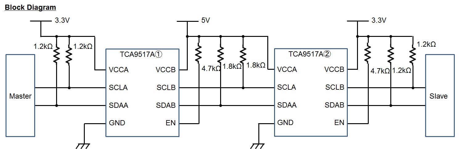
Customers are using the configuration for TCA9517A shown below.

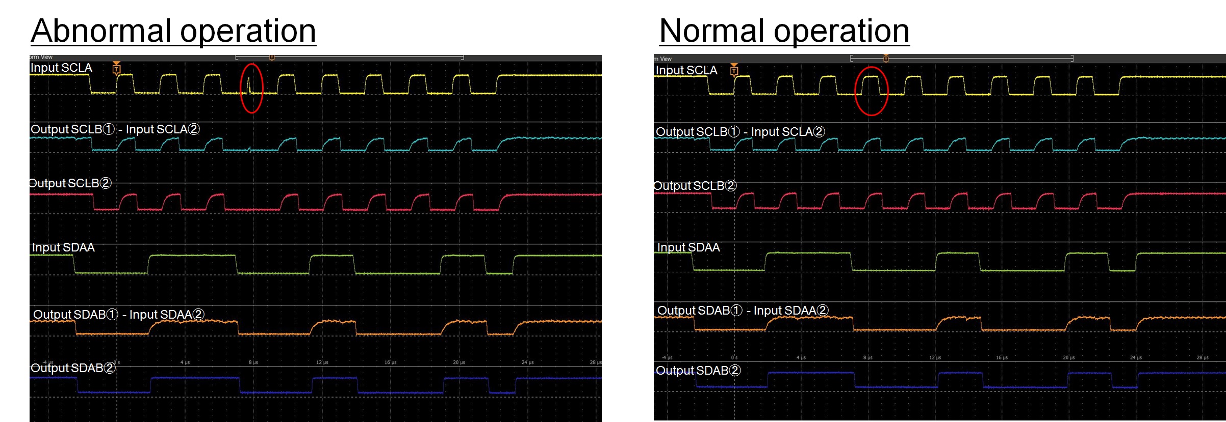
In that case, the waveform is as follows.

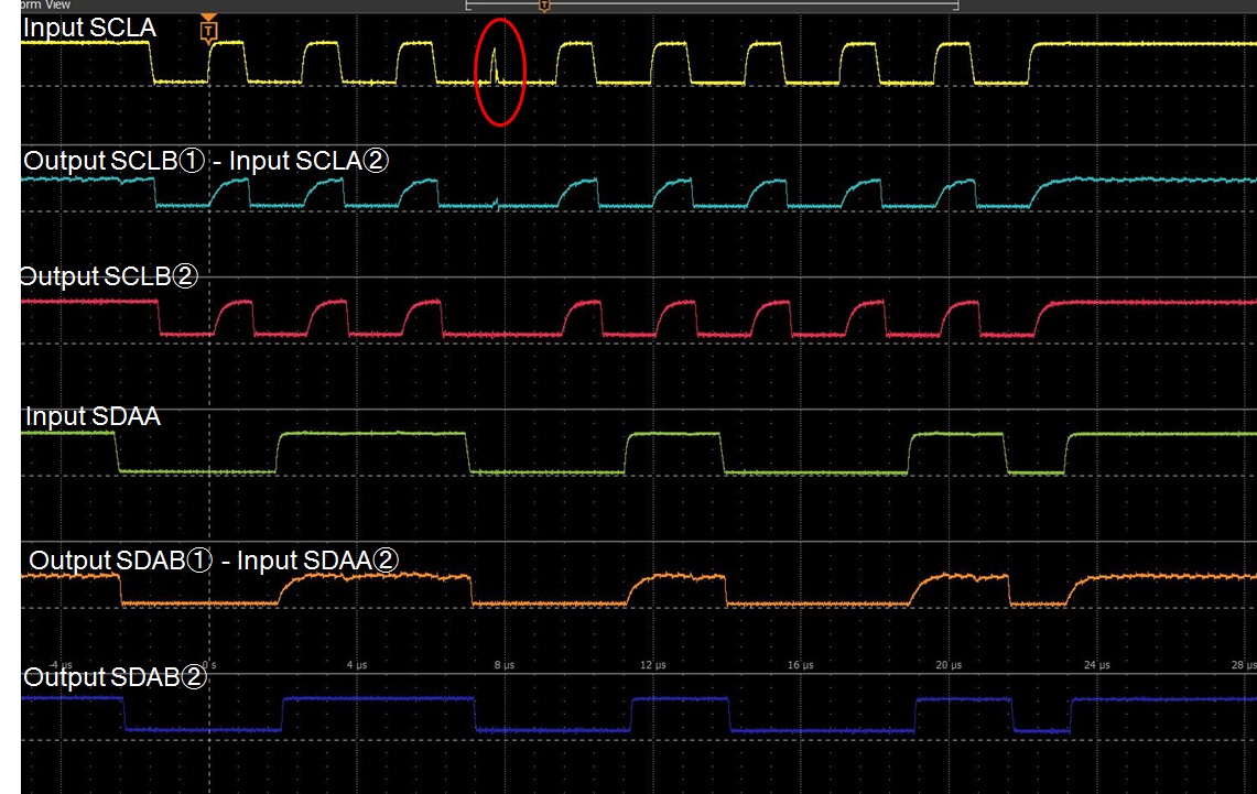
Input CLK is not input correctly. There may be a problem on the Master side.

But when using TCA9617B in the same configuration, the waveform was normal.

Do you know the cause? Are the input and output pull-up resistors appropriate?

The customer is in trouble and is rushing to find out the cause.
We need your support.

Best Regards,
Ishiwata

  • Hey Ishiwata-san,

    The master is the one generating 'input SCLA' correct?

    Is the waveform supposed to be low during the red circle or high? To me, it looks like the master released the clock signal and then takes control of the clock signal again. Our TCA9517A does not actively drive 'highs', the pull up resistor provides the highs. If the customer does not want to see a rising edge, he can change the pull up resistor on the clock of the master to a higher value than 1.3k. 4K ohms would probably get rid of that riding edge (make it lower than ViL) assuming the master takes control of the bus at the same time difference.

    The only other thing I could think of, is the slave is actually performing clock stretching. Is this what is happening?

    Thanks,

    -Bobby

  • Hi Bobby -san

    " The master is the one generating 'input SCLA' correct? "
    -> The master generates CLK. Like CPU.

    " Is the waveform supposed to be low during the red circle or high? To me, it looks like the master released the clock signal and then takes control of the clock signal again. "
    ->
    The customer wants to see the CLK that should be in the red circle.
    Normally, CLK is output but it is not output.
    Customers say the clock goes out when using TCA9517A.

    " 4K ohms would probably get rid of that riding edge (make it lower than ViL) assuming the master takes control of the bus at the same time difference."
    ->What does this mean against? Change pull-up resistance of EN pin?

    Best Regards,
    Ishiwata

  • Hey Ishiwata-san,

    Thanks for the picture of normal operation. So, looking at the two waveforms side to side. For some reason it looks like either the master on yellow is driving the line low, or the slave on 'output SCLB2' is driving the line low. Because I do not see a step in the "'output SCLB2'" I believe the issue is related the master.

    It may help if we change the 1.2k pull up resistors on the 3.3V bus on the master to something lower like 800. I am thinking this is somehow related to code and the master for some reason does not think the signal is driving high fast enough and decides to pull the bus low.

    "->What does this mean against? Change pull-up resistance of EN pin?"
    I misunderstood what was the waveform was supposed to do. Ignore my previous comment about the rise time.

    Thanks,
    -Bobby
  • Hi Bobby -san

    Thank you for your support.

    The customer verified Connect directly to slave from CPU without TCA9517A.
    As a result, similar CLK could be confirmed. It turned out that the problem is not TCA9517A by that.

    Best Regards,
    Ishiwata