This thread has been locked.

If you have a related question, please click the "Ask a related question" button in the top right corner. The newly created question will be automatically linked to this question.

PCA9548A: The device fails to switch sometimes, is this a known issue and are there workarounds?

Part Number: PCA9548A
Other Parts Discussed in Thread: TCA9548A

Hello,

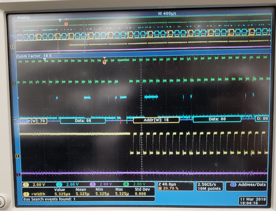
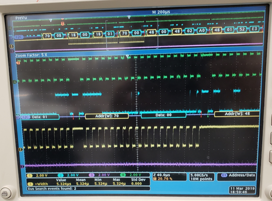
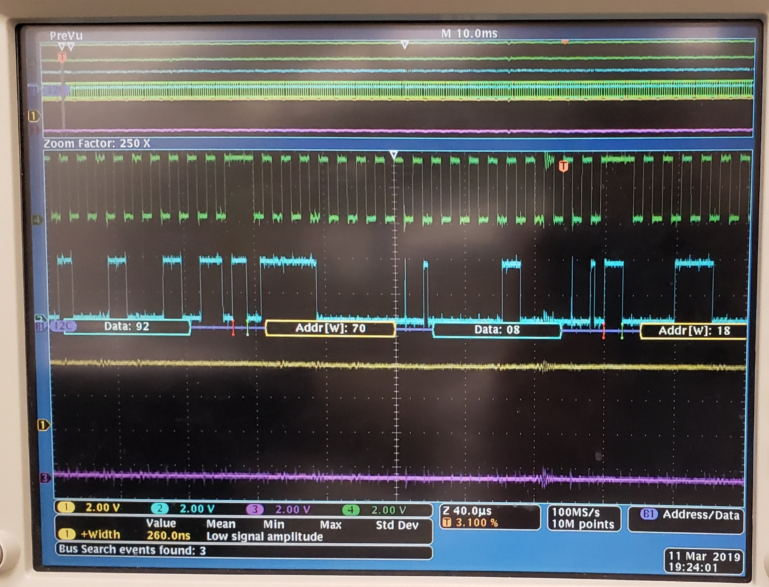
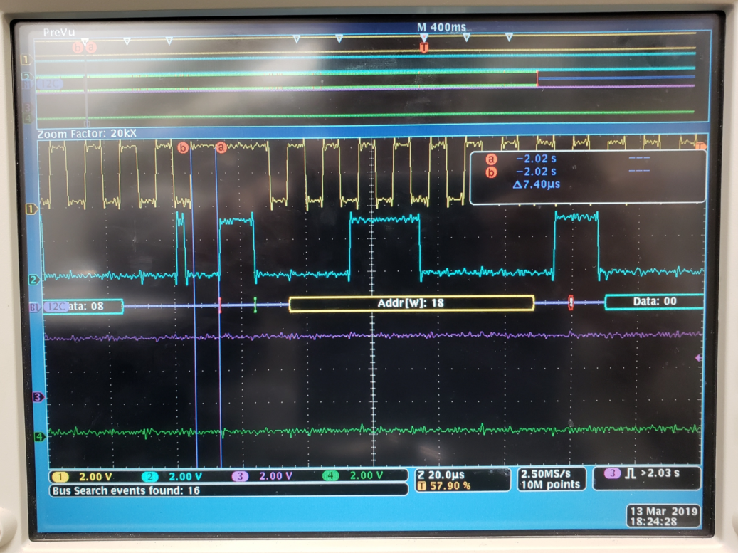
We have a system that uses the PCA9548A Switch, the device works fine most of the time however on occasion we have found that the device fails to switch.  We have verified the control register is correctly set but when monitoring the SDx, and SCx lines vs the SDA and SCL we do not see data or clock.  We can switch the device to another channel and then back and all is fine again.  I am wondering if this is  known condition and if there is an errata describing any recovery methods and also what the cause is.

Any help is appreciated.

  • Also, we have verified that when the failure occurs there is a complete control register transaction including a correctly timed Stop. We are operating in standard mode and have assured that the tsps parameter is correct as well. Note this is a very intermittent condition, but does happen and we are looking for some insight, and possible root cause, especially if this is a known condition.

    Thanks Again!
    Carlton
  • Hey Carlton,

    Do you have scopeshots of a transaction where the devices doesn't switch after you've given it a switch command?

    The only case I am aware of where this could happen is if you do not provide a stop condition on the I2C bus. This device waits for an I2C stop before it activates a channel after receiving a write command.

    "I am wondering if this is known condition and if there is an errata describing any recovery methods and also what the cause is."
    There is a way you could miss a command if the device's state machine is not reset properly. Make sure the device's Vcc ramp meets the power supply recommendation on page 20 section 11.1.

    If you run into issues with a bad PoR, you can reset the device manually by toggling the reset pin. Sending 9 clock pulses on SCL should also help reset the device's state machine.

    If you have a schematic of the device, I would also be happy to take a look at it to see if there is anything that pops out that could cause a problem.

    Lastly, have you tried using the TCA9548A device? The TCA line up is usually cheaper, same pin out, and fixes bugs from the previous family (in this case it makes the PoR restrictions much wider to make it easier to get a good reset upon start up).

    Thanks,
    -Bobby
  • Hi Bobby,

    Thanks for the quick response.  Unfortunately I cannot post the schematic, however I can say we have gone over the circuit itself very carefully to see that all is properly decoupled, the voltages are stable at Power Up, and that we manually reset the device prior to use as well.  

    For the most part the switch works fine, its just that every so often it fails to switch over to the selected bus, as if the command did not complete with a valid stop.  The following photos show a good switch to the selected bus, a good switch away from that bus, and then a failed switch.  We have a workaround, which forces us to retry the switch if we see a non response from the device on the SDx/SCx bus, and that works, I just want some more insight.  You mentioned that you have an updated part that looks like a drop in replacement, and I would assume it is because of design improvements, is one of those improvements because of this type of intermittent?  I will look into the possibility of using the newer part as a better than replacement, but for now I have existing boards populated with the legacy part.

    The top two traces are the SDA and SCL, the trace below that is the SC2  or clock of the selected bus.

    Regards

    Carlton

  • Hey Carlton,

    The last image does not seem to indicate a fail case if we are looking at SC2. The data you sent is 0x08 which indicates channel 3 is turned on and all the other channels are turned off. You do not have a probe watching channel 3. Were you able to verify that channel 3 was not active? (if you are trying to communicate through channel 2 then you need to send 0x04h).

    -Bobby
  • Forgot to address one of your other comments:

    "You mentioned that you have an updated part that looks like a drop in replacement, and I would assume it is because of design improvements, is one of those improvements because of this type of intermittent? " The TCA9548A did not address an intermittent connection, this is the first I've heard of this glitch.

    From the waveforms you sent, I do not see any thing that pops out. You may want to check your idle condition (how long did you wait before performing a start condition). I2C requires a wait time between stop and start to be 4.7us (standard mode) and 1.3us (fast mode). I doubt this is the issue but may be something to keep in mind. (time division in your graph seems to indicate 40us per div so you likely are meeting this)

    -Bobby

  • One other note to take a look at:
    Can you check to see what the set up time on the stop condition is? Standard requires 4us and 0.6us for standard mode and fast mode. This could be the difference between seeing a valid stop condition.

    Thanks,
    -Bobby
  • Hi Bobby,

    Attached shows the timing of the stop bit, and yes you are correct it is SC3 i am showing in all three previous photos not SC2 as indicated earlier.  My bad on that, but as you can see in the traces the switch to SC3 and off of it occur correctly, whereas in the last picture it does not switch to SC3.

    Here is the timing of the stop bit, i will look into the stop to start times to see if we are in violation.

  • Just checked the system and we are almost 11us between stop and start... (as you can see from the photo above too)...
  • Hey Carlton,

    Thanks for checking on the stop set up time.

    "as you can see in the traces the switch to SC3 and off of it occur correctly, whereas in the last picture it does not switch to SC3."
    Yeah, I noticed that. I figured you were looking at channel 3 since, the other two waveforms seem to indicate that as well. I do see the switch ACK when the data byte 0x08h is sent. The only other thing I could think of that would cause this is some kind of noise or something coupling onto the reset pin. Are you able to monitor the reset pin when the switch fails to actually switch?

    Thanks,
    -Bobby
  • Hi Bobby,

    I'll be setting that up and posting scope shots later today.  Thanks for that tip, when we re-read the data sheet we were puzzled at the Reset timing as there was some ambiguity.  We read it as the reset pulse can be as narrow as 6ns (tw), and that a Stop could be interpreted if SDA went High within 500ns max (trst). Then we read the trec value of  0 ns, and became puzzled as the waveform in the datasheet somewhat obscures what was written (instead of clarifying). 

    Can you elaborate on a reset scenario where a 6ns pulse occurred randomly (i.e. from noise), that is, would the chip think a Stop was issued if the SDA was high at the time?

    Your support is very much appreciated!

    Carlton

  • Hey Carlton,

    " when we re-read the data sheet we were puzzled at the Reset timing as there was some ambiguity. ......."
    The reset pin is mainly to get the device back into the default state (all channels turned off) in the event that SDA is latched low (this is called a stuck bus, there a multiple ways for this to happen) while one of the SDA channels is enabled. So the trst parameter you are referring to is the time it takes for the channels to be disabled (the main SDA channel is pulled high if the master is idle because no one else is controlling the bus). So if you hold reset low and released, you would expect that in 500ns the device's channels will all be disabled and communication to TCA9548A would be possible after this (previously it wouldn't be because you had a stuck bus). Essentially, you can use TCA9548A to isolate stuck buses with the reset pin feature.

    "Can you elaborate on a reset scenario where a 6ns pulse occurred randomly (i.e. from noise), that is, would the chip think a Stop was issued if the SDA was high at the time?"
    There could be multiple reasons why a reset pin could dip for a small amount of time. The main culprit I suspect would be crosstalk. If you have a trace that runs parallel to the reset trace either on the same plane or directly on top/below then the copper of the two traces plus the insulator between the two form a parasitic capacitor. With really strong drive strength, you can generate a fast di/dt which could cause current to temporarily flow from one trace to the next through the parasitic capacitance formed by the two traces. The faster the di/dt the greater the effect. You could potentially see your reset signal dip for a small amount of time, the weaker the pull up resistor is on the reset pin, the longer it takes for reset go back to a high state. So if this is the issue, then we would probably need to give the reset pin a stronger pull up resistor. I would also check to see if any signals are driving low (and parallel/cross the reset PCB trace) during the I2C transaction where we see the switch fail to actually switch. Because we see the TCA9548A ACK, I suspect if the issue is reset, it would occur shortly after the ACK.

    "would the chip think a Stop was issued if the SDA was high at the time?"
    Note: The state of the SDA/SCL pins do not matter to the reset pin, the reset pin itself simply resets the state machine and sets the channels to all be disabled like a power on reset/ powercycle.

    Before we start chasing this rabbit, we probably want to watch the reset pin closely. We want to zoom in to after the ACK during the failed switch. Make sure the o-scope is sampling this with enough resolution that we see this. If this is also the cause, making the reset pull up resistor weaker would also increase the chances of this happening.

    Thanks,
    -Bobby
  • Hi Bobby,

    To close this out, we did monitor the reset line over the weekend and the circuit did not trip on that once.  Note we still had the failures, but our corrective measures have accounted for them.  We had a high enough sample rate that we could see very clearly that the reset did not occur.  Anyway I want to thank you for your support.  If you don't hear from me again feel free to close this.

    Regards

    Carlton

  • Hey Carlton,

    Thanks for getting back to us.

    Just as an additional option, you can contact me at duynguyen@ti.com incase you have further questions/information you do not want to share online.

    We may also be able to perform failure analysis on the device to see if the device has suffered any damage which may be why you are seeing these glitches with the device. (if this is a route you want to take, email me and I'll put in you contact with one of our quality engineers).

    Thanks,
    -Bobby