This thread has been locked.

If you have a related question, please click the "Ask a related question" button in the top right corner. The newly created question will be automatically linked to this question.

TUSB522P: Application Queries

Genius 5355 points
Part Number: TUSB522P
Other Parts Discussed in Thread: TUSB8044, HD3SS3220

Hi Support,

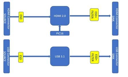
For TUSB522 application, do you have any idea for below issue?

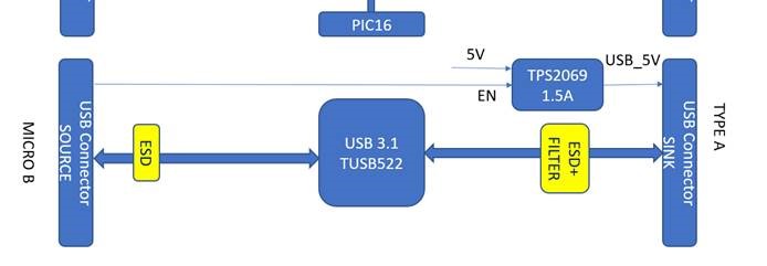
  1. When one USB3.0 port run as Host and Slave (connect with PC or Flash Driver), that means the 5V will be as input or output, so how can I protect the USB_5V? how to isolate it from the Host USB Power in?
  2. I found the TPDS3S014, but it is only for signal line ESD protection and output the safety USB_5V power.  It can’t be used for Host (PC) application because can’t detect the external USB input.
  3. Need we use the two parts as bi-direction for the USB_5V input and output?

Situation:

  1. Run USB as host – connect PC and detect, transfer data or receive command

2. Run USB as slave – active and drive the Flash Memory Stick for data saving

Thanks.

  • Ikon,

    Are you using a Type A port or Type C port? Is this a DRP (Dual Role Port) application? Could you provide a simple block diagram of this application?

  • Hi Malik,

    Please refer below block picture, we are using USB X 2 & HDMI X 2 PORTs total.

    Thanks.

  • Hi ikon,

    From you block diagram will only on source be connected at a time? If there is only one it seems you may be looking for a USB Hub, If so you may consider TUSB8044 or TUAB8020B.

    From your diagram it seems that data and power is always following form Source to Sink, is this correct? Could you explain further what the customer is trying to do? Are you using type-C ports for this application? Vbus should be present for downstream devices and can be passed from Source to Sink if it is not needed but need to be within USB spec. Normally For USB hubs Vbus is used to detect a valid connection for a USB host and then Vbus is re generated from external power for downstream devices.
  • Hi Malik,

    I added power limit for USB_5V with the on-boar-5V.

    Left side change to MICRO B connector, and use the OTG_ID as the EN pin to active the USB_5V.

    Working status: 

    MICRO B connect TO M320 MAIN BOARD

    TYPE A connect to PC USB / or FLASH MEMORY / or /USB WIFI ADAPTER

    Connection:

    1. TYPE A to PC, M320 run as device
    2. TYPE A to Device, M320 run as host and support the 5V /MAX 1.5A. (as USB3.0 STANDARD is 0.9A, and consider for the WIFI Adapter.)

    Thanks.

  • ikon,

    I will address the my concerns with the the connector separately. The major concern is that OTG is meant to work with USB 2.0 applications (DP & DM) and more with USB 3.0 (SSTX &SSRX). Is the application meant to meet full USB compliance? 

    Type A Connector: 

    • When trying to connect to a Host PC you will have a Type-A to Type-A, this is not allowed via the USB spec.
    • We recommend using a Type-C port here with HD3SS3220 which can act in DRP mode to get you the functionality of HOST or Device dependent on what is connected. It can also take can of enabling VBUS when in Host mode. 

    Micro-B Connector;

    • Will this side be completely proprietary to the M320? is the connector fixed as MicroB?
  • ikon,

    Is there any more support needed for this issue? If so please reply with any relevant details so that I can further assist you. For now I will be marking this thread as "TI Thinks Resolved". If you have resolved your issue, please post the solution to the original problem/post for others with similar issues.