This thread has been locked.

If you have a related question, please click the "Ask a related question" button in the top right corner. The newly created question will be automatically linked to this question.

SN65LVPE512: SN65LVPE512 EQ tuning question

Part Number: SN65LVPE512

Hi teams

My customer using SN65LVPE512 in their new design and encounter some issue.

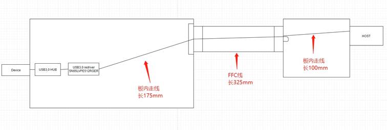
The device location is shown below. They placed re-driver close to the USB plug(USB device) and trace length is around 0.6m.

Included 175m in first PCB board, 325mm Flexible Flat Cable and 100mm in the second board.

When they set the EQ=0dB, the host can't connect the device. 

Now they set EQ=7db and the connection is success.

Below is my question:

  1. Customer original purpose to add this re-driver is want to enhance the external signal that attenuates by long cable. But if the trace inside the product is long too do you have any method to optimize the performance?
  2. Do we have a guideline about how to tuning the EQ?
  3. Do we have any method to test the signal integrity in host side? 

  • Gabriel,

    1. If the trace inside the product, between the Host and SN65LVPE512, is too long and completely fixed there is not much optimization to be done with SN65LVPE512 other than trying the three EQ settings. For long cable case OS and DE become important, has customer tried testing long cable case? Is it possible for the customer to change any setting with the USB Host?

    2. Generally you would want to using the lowest EQ setting that gives desirable margin with the standard SUB near end eye mask, in this case.

    3. Capturing a Eye diagram using a high speed scope is a good place to start. This would involve using a high impedance probe and probing directly on trace or test point in between host and SN65LVPE512. This will show you the signal performance of the host and include losses from host until the test point. I recommend probing multiple points in order to understand what is the major contributor to the signal integrity issues. To start, please probe before and after FFC cable to understand the signal that is entering SN65LVPE512.

    Could you explain this application in more detail? where is the USB connector after SN65LVPE512? Could you mark this on the image above?
  • any more question?
  • Gabriel,

    Is there any more support needed for this issue? If so please reply with any relevant details so that I can further assist you. For now I will be marking this thread as "TI Thinks Resolved". If you have resolved your issue, please post the solution to the original problem/post for others with similar issues.