Part Number: DS90UB925Q-Q1
Hi Team,
We want to realize the touch screen control of the reverse channel through DS90UB925 + DS90UB928. Please evaluate the feasibility?
If it is not feasible, we can replace the touch screen scheme which has been verified before with DS90UB927 + DS90UB928.
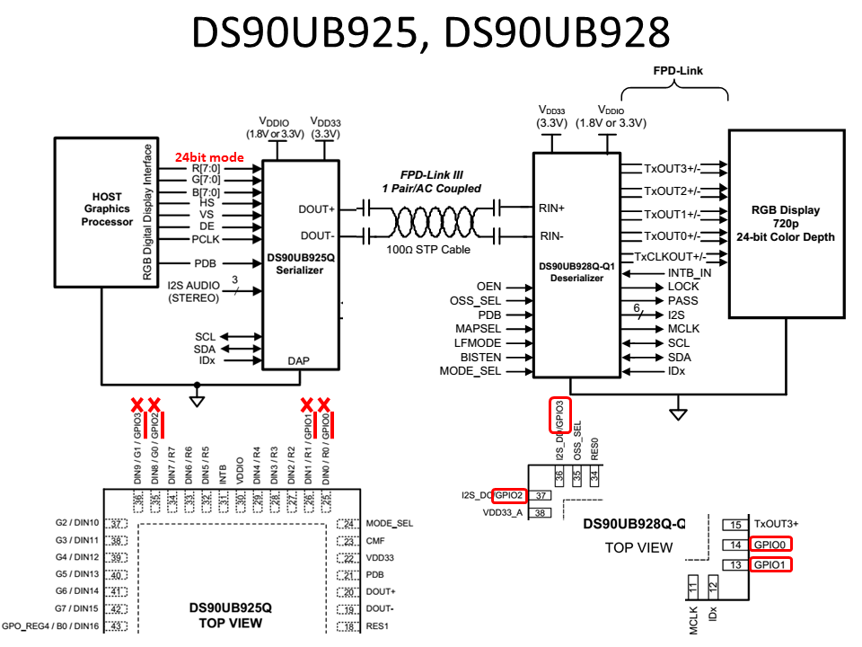
1. DS90UB925: It needs to be set to RGB888 24 bit mode. DS90UB925 RGB888 data occupies GPIO0~2 pins and can only be connected to GPIO6~8 pins (DS90UB925 pins can only be used as input).
With the remote through mode, the corresponding DS90UB928 is also connected to the LCD backlight and touch screen reset via GPIO6-8.
2. Touch screen requirements: I2C SDA/SCK, touch screen reset (DS90UB9), touch screen interruption INT, LCD backlight ON/Off control, connected to DS90UB928,
(1) SOC I2C SCK (DS90UB925) -->(DS90UB928) - - touch screen interface;
(2) SOC I2C SDA (DS90UB925) -->(DS90UB928) - - touch screen interface;
(3) SOC Touch Screen Reset (DS90UB925 GPIO6 Input) --> Touch Screen Interface Reset Input (DS90UB928 GPIO6 Output) - - Touch Screen Interface Reset Input;
(4) SOC touch screen interrupt input INT (DS90UB925 INT output) --> DS90UB928 INT input - - - touch screen interface interrupt output;
(5) LCD backlight ON/Off output control (DS90UB925 GPIO7 input) --> (DS90UB928 GPIO7 output) - - touch screen interface input;
like this below:


