This thread has been locked.

If you have a related question, please click the "Ask a related question" button in the top right corner. The newly created question will be automatically linked to this question.

DS90UB928Q-Q1: GPIO noise question

Part Number: DS90UB928Q-Q1
Other Parts Discussed in Thread: DS90UB929-Q1, , TFP410

Hi sir.

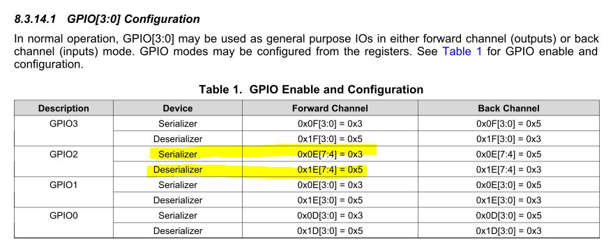
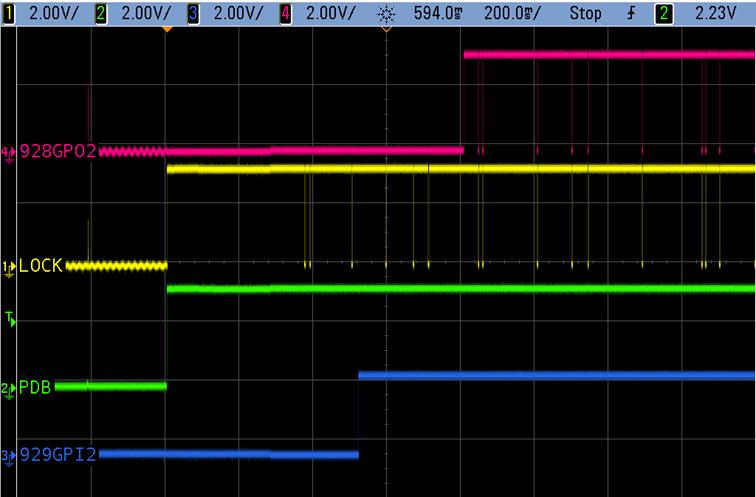
We use UB928 to set GPIO 2 to GPIO mode. But we measured the noise before setting GPIO 2 to GPIO mode.

Until UB929 and UB928 link and set to GPIO mode after about 2 seconds noise will disappear. Can this Noise be solved?

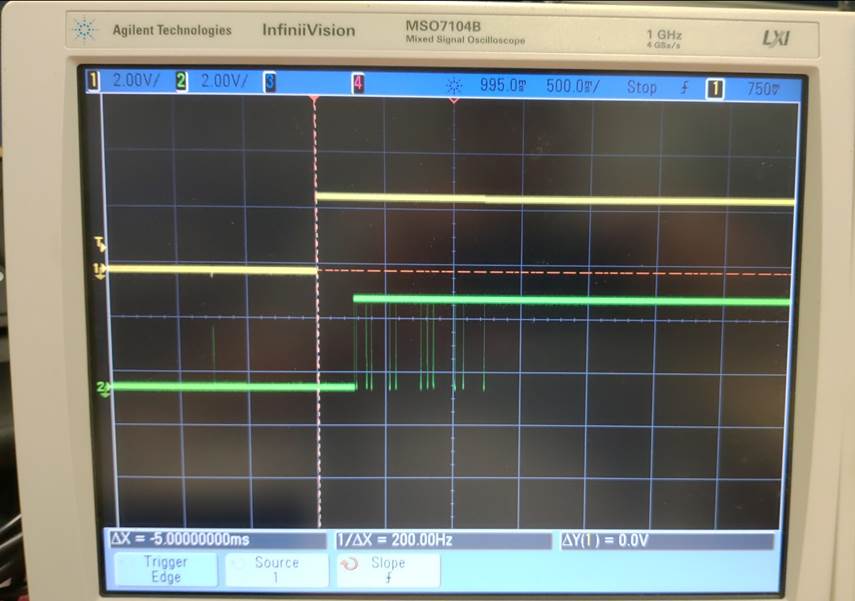
Channel 1, UB928 IDB pin(Power Enable)

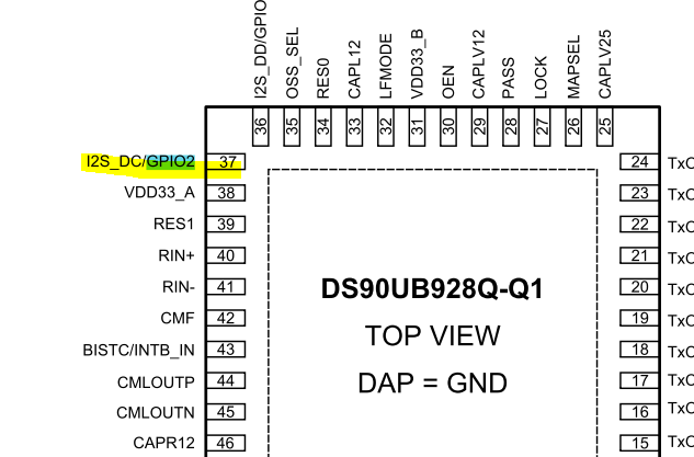
Channel2, UB928 GPIO2

  • Hey AJ,

    Can you also probe LOCK on the 928 during this startup?

    Best Regards,
    Casey
  • Hello,

    If you are trying to control the 928 from the remote Serializer, the forward channel, and LOCK status are needed.  

    GPIO2. if you use the OEN input Low, and OSS_SEL Low, the GPIO is forced low through Table 5 in the datasheet.  

    GPIO2 when the Forward Link is active, or the Local I2C (at the 928 is active), can be changed through register controls.

    pg46 datasheet, Register 0x1E has the GPIO2 control, on power up GPIO2 is in the I2S function, it can be reprogrammed as a GPIO through this register, or controlled by the remote serializer.  

    Before you reprogram register 0x1e, the GPIO2 is a default power on function.   If you want to not see the pulses on GPIO2, set OEN = 0, then program GPIO2 for output, with a logic '0'. then set OEN = 1.

    Regards,

    Joe Quintal

  • Dear Joe / Casey.

    Good day.

    It seems that the noise of GPIO 2 is affected by LOCK. After about 2 seconds, LOCK is stable and there is no noise. GPIO 2 is also normal.

    Why does LOCK have noise at the beginning? is this normal? Can this problem be solved? Thanks for kindly help~

  • Hello,
    Although you asked about GPIO noise, in your last oscilloscope snapshot, it is not normal to have a device continue to be out of lock
    and in lock. You need to investigate what is causing the loss of lock, and fix that first. We expect LOCK to assert several ms after PDB
    is releeased. After the initial 0->1 transition on lock, there appears to be a place where the 928 GPIO2 is programmed to follow an FPDLink input
    GPIO or I2C command. We can't tell the GPO2 is being directed as a 0 during the non-lock period, because it is already a logic '0'.
    GPIO1 and 2 are shown in Table 8, if the GPO2 is forwarded from the serializer, when Lock is lost, its possible the Link is retrying to establish control.
    Regards
    Joe Quintal
  • Dear Joe.
    Good day.
    Can I use UB929 to control the UB928 TMDS output on or off? If so, please tell me how to control. In addition, the UB928 Lock output can also be controlled by UB929? Thank you~
  • Hey AJ,

    It is possible but it will not solve the root cause of your problem. I would suggest working to understand the signal integrity if your link using the MAP analysis tool first. You may adjust the AEQ floor value based on the MAP tool result to improve initial lock behavior. Finally, you can force the 928 LVDS outputs off by setting register 0x4A bit 0 = 1

    http://www.ti.com/lit/ug/snlu243/snlu243.pdf

    Best Regards,

    Casey 

  • Hello,

    The DS90Ux929 - HDMI Serializer, converts HDMI TMDS to FPDIII RGB data.  See section 8.1 of the 929 datasheet.

    The DS90UB929-Q1 converts an HDMI interface (3 TMDS data channels + 1 TMDS Clock) to an FPD-Link III
    interface. This device transmits a 35-bit symbol over a single serial pair operating up to 3.36Gbps line rate. The
    serial stream contains an embedded clock, video control signals, RGB video data, and audio data.

    The DS90Ux928 - OLDI Deserializer, converts the FPDIII RGB data back to OLDI LVDS video, and audio data.  See section 8.1 of the 928 datasheet.

    The DS90UB928Q-Q1 receives a 35-bit symbol over a single serial FPD-Link III pair operating at up to 2.975
    Gbps line rate and converts this stream into an FPD-Link Interface (4 LVDS data channels + 1 LVDS Clock).

    1) So I will answer the first question ( HDMI in Serializer <-> FPD3 <-> Deserializer HDMI out

    You would use the DS90Ux929 or DS90Ux949 Serializer for HDMI to FPDIII.

    You would use the DS90Ux928 Deserializer (FPDIII to OLDI) for an OLDI LVDS output

    You would use the DS90Ux926 Deserializer (FPDIII to RGB) and a TFP410 converter from RGB to HDMI output

    2) There are several schemes to blank the data path.

         see app note AN-2198 for programming the Pattern Generator.  You can preprogram the panel size, and custom black color, you only need one register write 

         for enable to disrupt the video with the test pattern.

         a1) Serializer - program the serializer Pattern Generator for the desired Deserializer Display panel, send black color as custom color.  Enable pattern generator

         a2) if the device is a DS90UH929 - the AVMute feature can be used, if the Deserializer DS90UH926, 928 is capable of utilizing AVMute.  

          b) Deserializer - program the deserializer Pattern Generator for the desired Display panel, send black color as custom color, Enable Deserializer pattern

              generator.   

        c) there are methods to take down the Forward Channel data path, or Reset the Deserializer PLL, these are not considered, as more initialization is needed

             to recover from tearing down the link or clock structures.

    3) The UB928 OLDI Deserializer, 

       section 8.4.1 has the Clock and Out Status, normally the LOCK indicator follows Table 5 in the Datasheet.  If you would like to programmatically change the status, the suggestion is to read the LOCK status remotely over I2C registers.  The Host Processor (connected to the Serializer), reads the LOCK status from the Deserializer,  computes a software controlled LOCK, programs a local or remote GPIO which is output on the Deserializer.

    Regards,

    Joe Quintal