This thread has been locked.

If you have a related question, please click the "Ask a related question" button in the top right corner. The newly created question will be automatically linked to this question.

TPS65987EVM: SINK Demo Setup - Cannot Connect to GUI

Part Number: TPS65987EVM
Other Parts Discussed in Thread: TPS65987D, TPS65987, TPS65988

Hello,

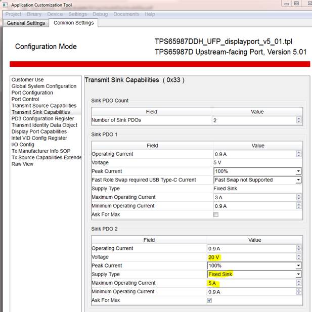
I am working to setup a demo to evaluate off-the-shelf USB type C PD chargers. I would like to connect to the GUI and adjust the voltage that the SINK asks for from the charger.

I have downloaded the TPS6598x Configuration Tool (from: http://www.ti.com/tool/tps6598x-config) and have looked at the TPS6598x Ultilities Tool Users Guide (http://www.ti.com/lit/an/slva701c/slva701c.pdf) as well.

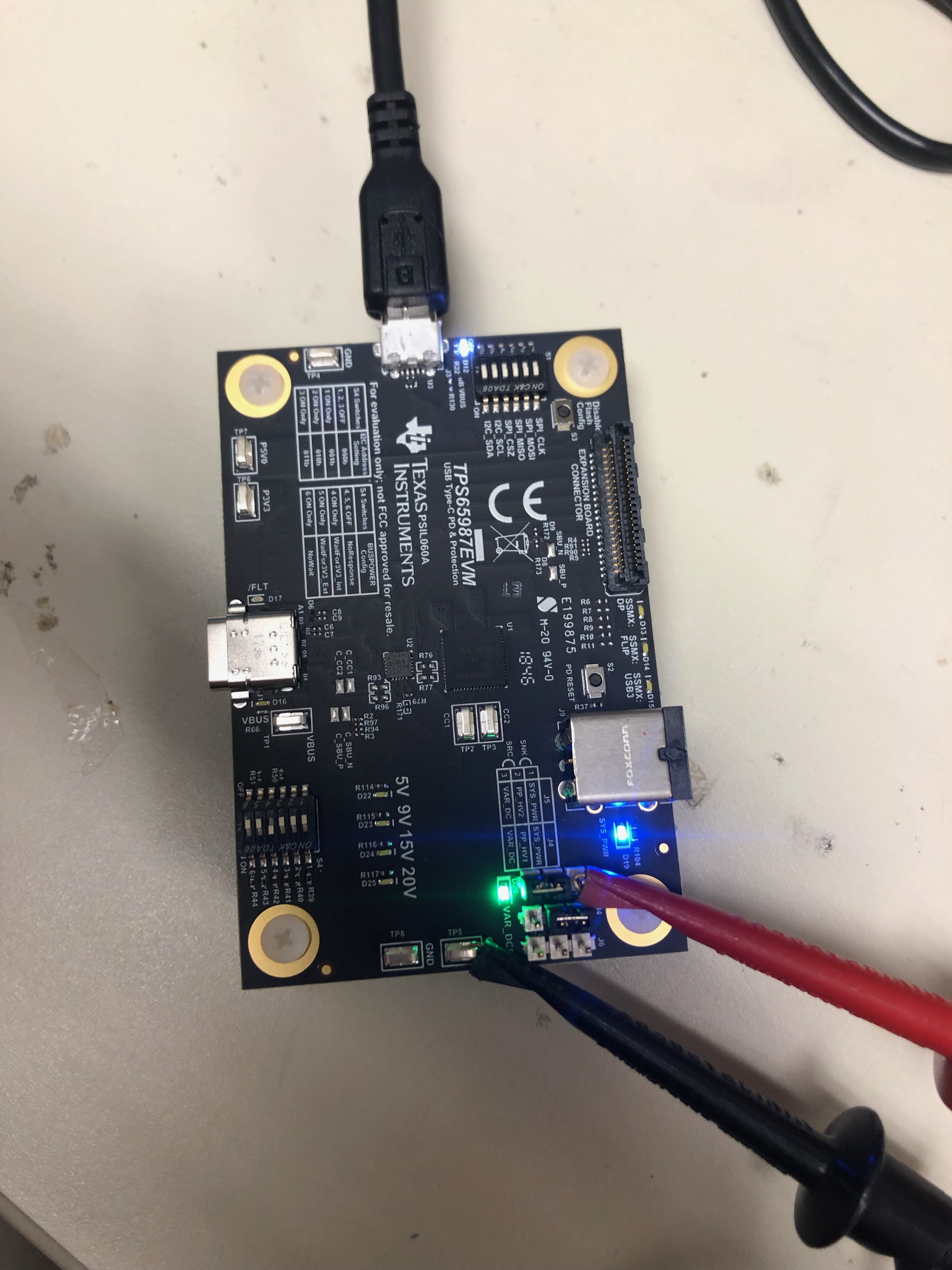
With the TPS65987EVM connected to a 20VDC power supply and the USB connector plugged into my laptop (running windows 7) - I am unable to communicate with the board.


See below for the EVM setup:

I was able to see all the com ports:

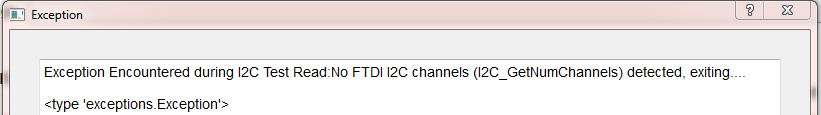
But here was the error when I tried to I2C test read:

Please provide any help as to how to get my customer up and running!

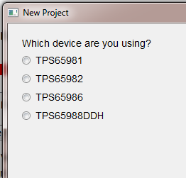
Lastly, when I click new project, the TPS65987 does not show up as a supported device - is this tool no longer the correct one for the TPS65987D?

Thanks,

Reed Kaczmarek

  • Hello Reed,

    This seems like you are having issues with the FTDI drivers. You can follow this E2E thread to reinstall new FTDI drivers that have a better chance of working with your laptop.

    e2e.ti.com/.../2293327
  • As far as the TPS65987D projects, click on the TPS65988 and continue until you see the large drop down box of firmware templates
  • Hi Adam,

    Thanks for the advice. I tried to uninstall and reinstall FTDI drivers twice (once with CDM21226 and once with CDM20824). Neither worked.I followed the directions found here: FTDI Driver install.pdf

    What is the best way to test the connection? I have been going Debug-> Configure I2C/SPI Adapter Settings -> Sweep I2C address range for response (USB to I2C = FTDI).

    If there is another thing for me to try or a better method to test, please let me know.

    Thanks,

    Reed

  • Hi Adam,

    As I await your response on the FTDI. My customer has been able to get the connection to work with his laptop.

    The goal is to setup the EVM as a SINK and then to adjust the maximum voltage the EVM asks for. For example, we want to setup as a sink at 20V/5Amps and then we want to run another test as a SINK at 12V/5A. The charger side is a commercially available USB-C PD charger capable of 20V,15V,12V,9V,and 5V.

    What is the best method to implement this test setup? Would it be to use template "TPS65987DDH_UFP_displayport_v5_01.tpl" and modify so that there are 2 SINK PDOs as shown below? 

    After this program is flashed I would hope for a 20V/5A negotiated power supply. If I change Sink PDO 2 for 12V, would that be the only change needed for the charger to negotiate a 12V/5A connection?

    Thanks,

    Reed

  • Hello Reed,

    Yes that is the best way to try and test FTDI functionality. Unfortunately, I do not have any other recommendations on fixing the FTDI drivers expect to remove them and to try installing different versions of them. Also try different USB ports within your system if you have not already done so. I know for me, the FTDI connection only works on one USB port on my laptop, so maybe something similar is occurring to you.

    As far as changing the sink capabilities of the EVM, the method you outlined above is the correct process. I'm assuming that the charger you are using has a captive cable, but if not, make sure that the cable you are using can support 5A.

    Hope this helps answer your questions. If so, please click THIS RESOLVED MY ISSUE