This thread has been locked.

If you have a related question, please click the "Ask a related question" button in the top right corner. The newly created question will be automatically linked to this question.

SN75DP130: Google NB issue

Part Number: SN75DP130

Hello

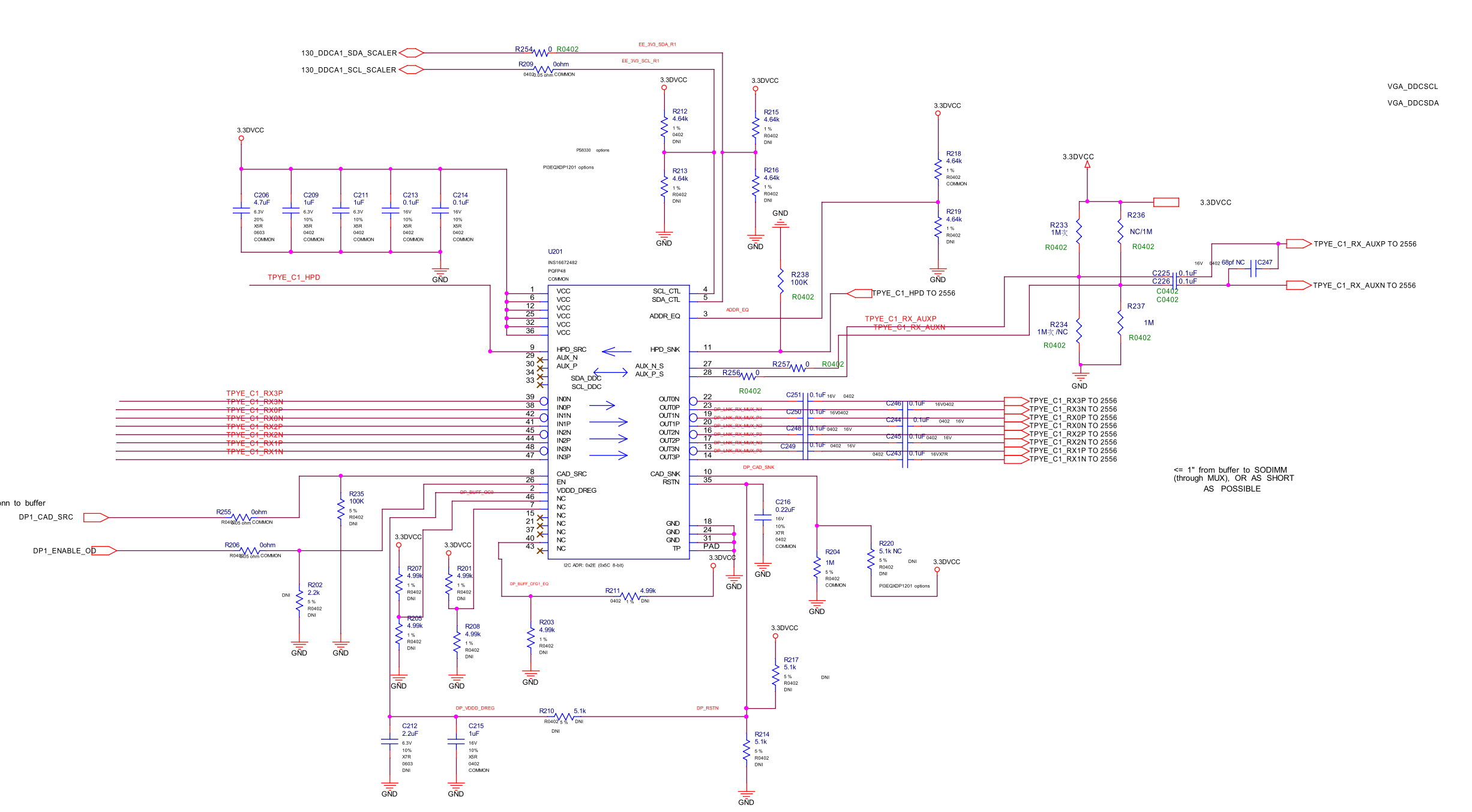
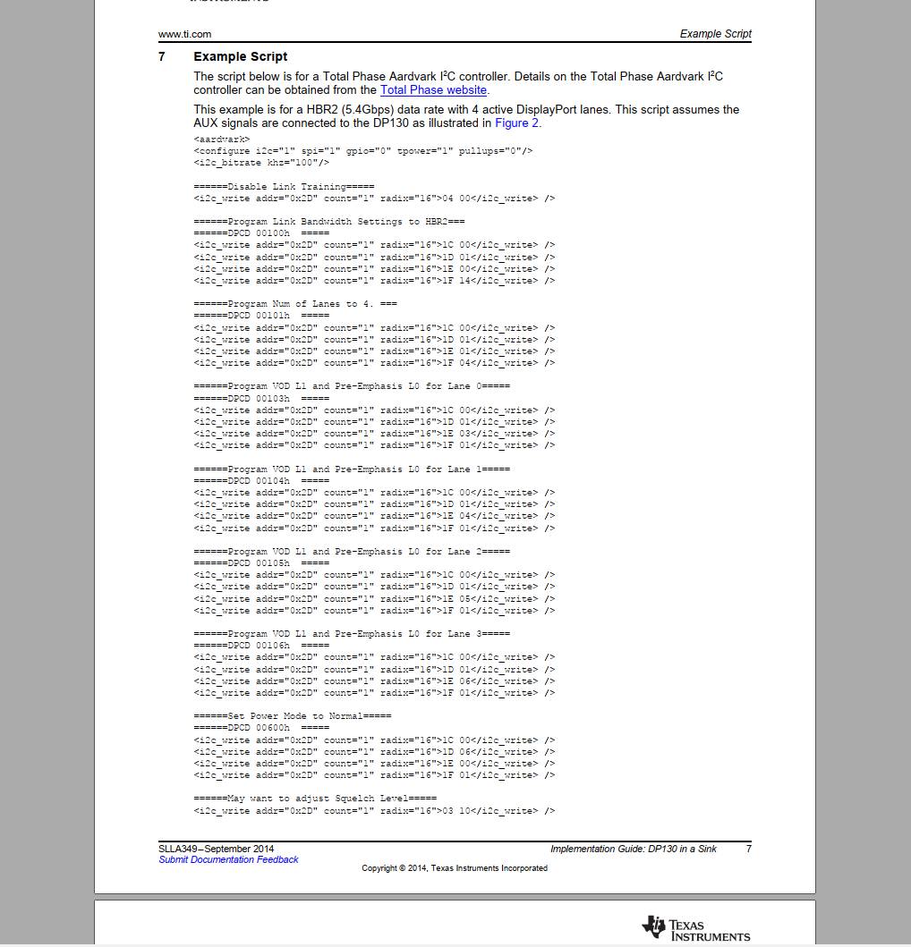
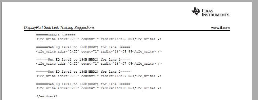
           Customer use DP130 default setting. Testing other NBs, DP signal will smoothly light up the Panel after re-driver. But if use Google NB, customer find two lane DP signal sent to DP130 input. But there is no DP130 output signal so can not light up Panel. Could I know what is the issue root cause? Thank you. 

BR

Patrick

  • Patrick

    Can you please share their schematic? Can they also dump out the DPCD register value?

    Thanks
    David
  • Hello David

                 Please refer to below. Customer dig out if NB send out 1 lane or 2 lane DP signal that can not light up panel on any NB. Just only 4 lane DP signal work normal. Please help check it. Thank you. 

    BR

    Patrick


  • Patrick

    If 4 lanes work, but 1 lane or 2 lane does not work, then there are two possibilities

    1. Lane communication over AUX is not correct, source, DP130, and sink all need to be set to 1 lane or 2 lane.
    2. Lane mapping to Type C connector is not correct.

    For #2, can you please share the connection on both the input and output side? I assume this is a DP sink application?

    Thanks
    David
  • Dear David

                   Yes. it is sink application. Please refer to below. Could you help what is issue root cause? Thank you. 

  • Patrick

    1. Lane communication over AUX is not correct, source, DP130, and sink all need to be set to 1 lane or 2 lane.
    *** Do they have a CC and AUX protocol analyzer? They need to look CC log file to see 2 lane DP mode is being requested(multi-function bit is enabled). They then need to look at the AUX log file to see source, DP130, and sink all set to 2 lanes.
    2. Lane mapping to Type C connector is not correct.
    *** For DP 2 lanes, please probe both side of MUX and DP130 output, are they seeing DP signals only on DP0 and DP1?

    Thanks
    David
  • Hello David

                 Customer follow example tp setting just only blue line difference on DPCD 100h set to 0A(HBR). Thank you. 


    BR

    Patrick

  • Patrick

    In DP 2 lane mode, can they probe DP lane 0 and lane 1 on both side of mux and the output of DP130 to make sure there is data on lane 0 and lane 1?

    Thanks
    David
  • Hello

    Customer test one lane by one lane. They send LAN0 signal and others lane just send clock to DP130. DP130 has LAN0 signal on output. While send LAN1 signal and others lane send clock to DP130. There is no LAN1 signal on DP130 output.

    Per schematics, LAN3 signal connect to DP0/DN0 pins of DP130. LAN0 signal connect to DP1/DN1 of DP130. DP130 is on default setting. If send four lane, DP130 can output signal to scaler normally.


    1. What is the issue root cause of no signal after DP130 for above testing?

    2. After link training, DP0/DN0 and DP1/DN1 of DP130 will enable, DP2/DN2 and DP3/DN3 will disable while source send two lane signal?

    3. If disable link training, DP130 can set all lane on to solve this issue?


    BR
    Patrick

  • Patrick

    Where do they send the signal, at the DP130 input or at the Type C connector input?

    When not seeing LAN1 signal, are they not seeing at DP1/DN1 of DP130 output? If they are not seeing LAN1 signal, are they seeing the clock signal?

    Thanks
    David
  • Hello

    Customer use test equipment send one lane by one lane signal form Type C connector. They mention looks has input signal of DP130 but has no output signal of DP130. What is the root cause for it? If it is related Lane mapping issue, that should be no any signal input to DP130, right? Thank you.

    BR
    Patrick
  • Patrick

    Can they disable DP130 squelch by writing a '1' to bit 3 of register 0x03h and see if they can get an output?

    Thanks
    David