This thread has been locked.

If you have a related question, please click the "Ask a related question" button in the top right corner. The newly created question will be automatically linked to this question.

DS90LV031AQML: Part all channel falut with vacuum condition

Part Number: DS90LV031AQML

We had an error during the Unit(Thermal Vacuum) test.

The same error occurred this parts(5962-9865101QFA : DS90LV031AW-QML) in three of the four(75%)

on the same board.

We think of this part (5962-9865101QFA : DS90LV031AW-QML) as cause of the error.


So, please request the manufacturer to check the following issue.


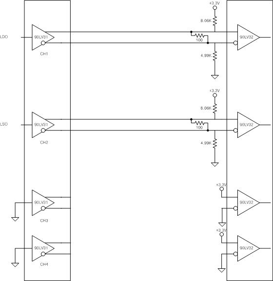
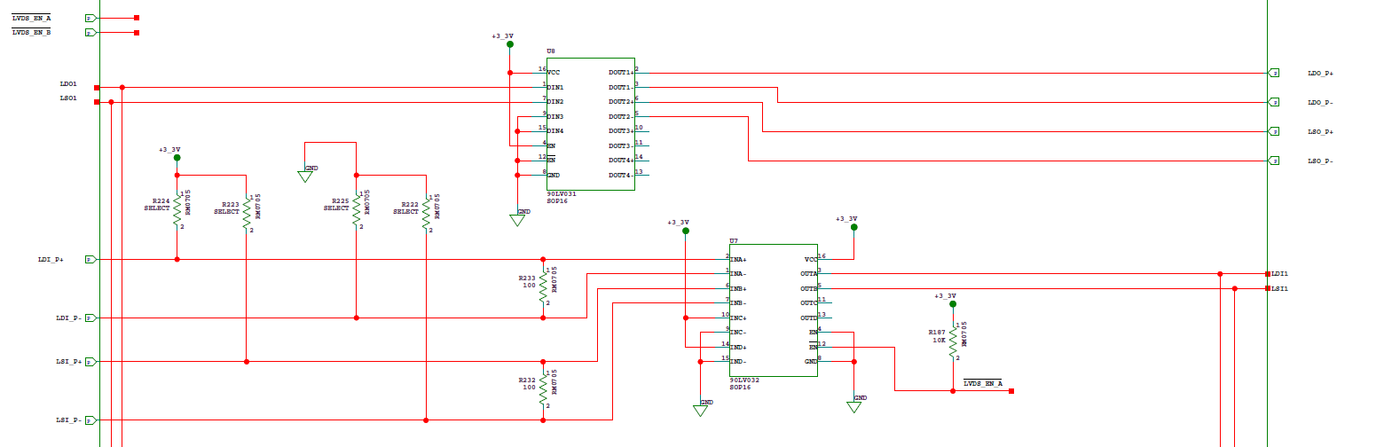
1) In failure situations, the circuit configuration is as follows.


external_image


2) After the failure, the output of driver(DS90LV031) was measured at -0.16V.

  All four channels(CH1, CH2, CH3, CH4) were equally output -0.16V. (+/- Pin, All same situation)


3) Part(DS90LV031) was separated from the board and remeasured output voltage.

 We also tested with 3.3V & 0V to input pin.

 But, all four channels(CH1, CH2, CH3, CH4) were equally output 0V. (+/- Pin, All same situation)


4) Like circuit configuration, we didn't use driver CH3, CH4.

   Although we didn't used dirver CH3, CH4, we wonder why the channel broke down. 

5) We alreay know missing design for unused input pin (recevier).

Please give us responseas below.


Ques.> Which impact is given to driver,

         Is it possible to check the output voltage with 0V on the CH3, CH4 of the Driver(DS90LV031)?

         Don't consider about signal distortion.


Please check and send us reply as soon as possible.

  • Sujin,
    Unfortunately the image showing schematic did not get posted.
    In order to post an image, click on the "Insert Code, Attach Files and more..."
    Then select an image or file with the paperclip icon to insert.

    Based on this limited data, what was state of enable signals for application and during testing?
    Regards,
    Wade
  • Sujin,

    This seems very unusual.  The schematic shown should not be harmful to the drivers.

    Are there any of the issues?  Power supply spikes or overvoltage?

    What temperature in the chamber?   Duration?  Is there any thermal dissipation through board?

    Did the device start out working, then fail?

    Your schematic does not show biasing of the enable lines.

    Did these units get sourced from a TI authorized distributor?

    Regards,

    Wade

  • Sujin,
    Have you resolved your issues? Since I have not heard back, I am going to close this post.
    It will re-open if you reply with more details.
    Regards,
    Wade
  • Test Condition is as belows.

    Temp : 30 ℃


    Pressure : 1st Test [ 1.7*10^-7 mbar] -Thermal Vacumme chamber Operation time 10 hours

                      2nd Test [ 5.5*10-6mbar] -Thermal Vacumme chamber Operation time 10 hours

                      3rd Test [similar to 1st and 2nd condition] -Thermal Vacumme chamber Operation time 10 hours

    Part Failure Number : 3 Times


    We tried thermal vacuum test surveral times.

    1st and 2nd test failure is detected when we turn on DUT.

    3rd test failure is detected on testing.

    Some failure parts are same postion, but we think fault postion is ramdom.

    Our DUT use many IC, but 90LV031 only destroyed this thermal vacuum condition.

    Althought we operate DUT serveral thousand hours on ambient condition, but it works only 10hours on thermal vacuum condition.

    Do we forget some caution about thermal vacuum condition?

    We bought parts from Alter which is parts supplier.

    Thanks for your answer.

  • Sujin,
    I have a couple comments.
    Is the boards temperature being measured during the test? You mention 30C. How is this controlled? Is the PCB controlled to 30C? Any board level temp measurements?
    What is the load on the used drivers? 100ohm?

    You are using Class Q devices for vacuum testing. Presumably for space use? We have Class V space qualified devices available: www.ti.com/.../DS90LV031AQML-SP

    We have no returns on this device within the last 3+ years (only data available).

    You mention parts supplier Alter. I don't believe this is a TI authorized distributor. Can you provide more information? Can you provide their website?
    If devices are re-screened, this voids the TI warranty.

    Most likely the devices are experiencing some form of electrical overstress during the vacuum testing or prior to vacuum testing.

    On a side note, your receiver unused channels are not adhering to recommended biasing for unused inputs. The datasheet indicates they should be left unconnected as they are internally biased to failsafe conditions.

    Regards,
    Wade
  • Another comment.
    With respect to the driver load. Is the receiver using the same ground reference as the driver?
    There can be cases where a ground loop is created that can impact operation and/or reliability.
    Regards,
    Wade
  • We monitored mechnical frame to 30 celsious.

    PCB size is 250mm*250mm and board power dissipistion is about 5V*0.7A.

    Actually we not controlled temperature only controlled vacuum

    It rised temperature by itself because DUT is power on.  (Test Lab Temp : 24 celsious)

    First we planed set  vacuum condition, and then control temperature.

    But part failure on vacuum was detected ,  so we stopped test.

  • As upper block diagram, we designed 100 ohm parallel resistor and, 8.06K pull-up, 4.99K pull-down

    And it is same that driver GND & Receiver GND.

  • Sorry for late reply, I have been out on vacation.

    Sujin,
    I don't see anything wrong with your biasing and setup. This should not be damaging to the device.
    Exposure to vacuum should not impact electrical performance of device.

    Exposure to vacuum will limit the ability for device to dissipate heat through the air. If device is not mounted to board to allow conduction of heat to the board, then it may be possible that device is overheating and not allowing enough cooling through the leads or through board when in vacuum.

    You mention 0.7A at 5V.
    This device operates at 3.3V. Did you mean 3.3V?
    How many devices are being supplied by the 0.7A? Do you know the dissipation of the Driver?

    Can you place thermocouple or other means to measure temperature of the device while under vacuum?
    Can you apply thermal paste to board to insure good conduction to board from device(s)?

    Other possible option is that devices were electrically over stressed by non warranted third party rescreening.

    Regards,
    Wade
  • Sujin,
    Any update?
    Thanks,
    Wade