Part Number: DS90UB926Q-Q1
Hello Sir
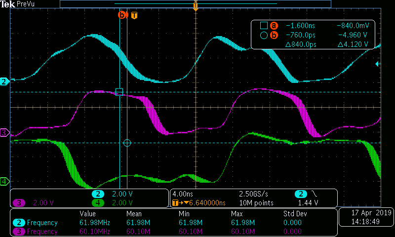
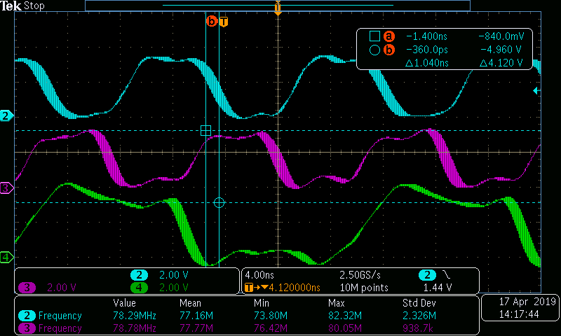
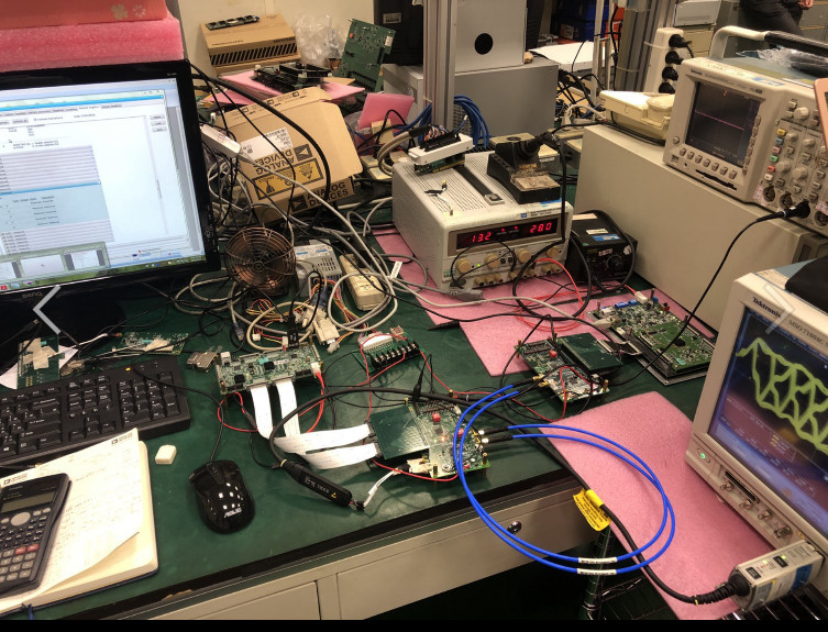
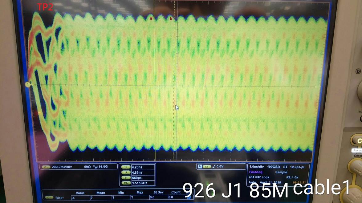
I used the 925EVM with the 926EVM pclk 85M to measure the TP2 and TP3 (CMLOUT) signals.
The signals obtained did not meet the datasheet specifications. Is there any thing that we ignored? Thanks for kindly help~

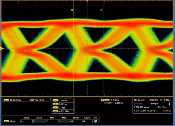
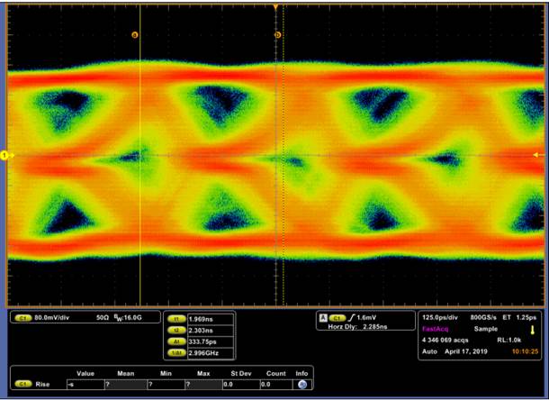
TP2
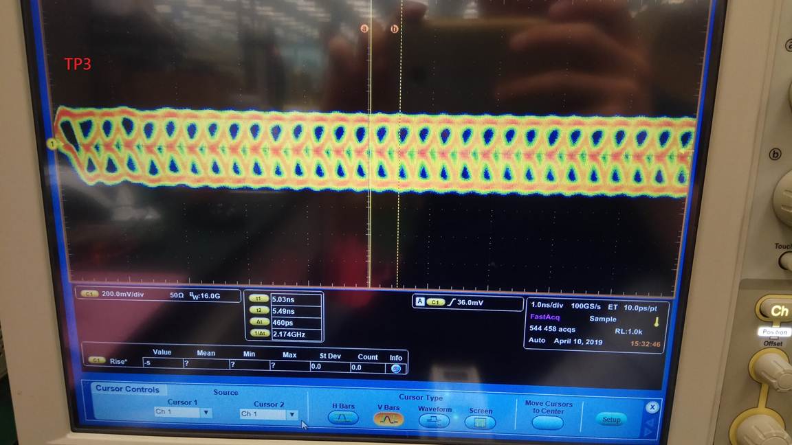
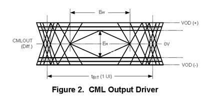
TP3