Part Number: DS90UB954-Q1
Other Parts Discussed in Thread: ALP, USB2ANY
Tool/software: Linux
HI,
I enable Pattern Generation ,when I set reg.0x33(CSI_CTL) to 0x01,Pattern Generation work well ,csi2 clk lane and data lane both have signal and I can cee color bar.
But when I set reg.0x33(CSI_CTL) to 0x03,Pattern Generation not work. I've checked the signal of csi2 clk lane and data lane. data lane have signal ,.but csi2 clk lane no signal and can't see color bar.
When I enable Pattern Generation with CSI continuous clock mode. Do I need to set up other registers? or Are there other places to pay attention to?
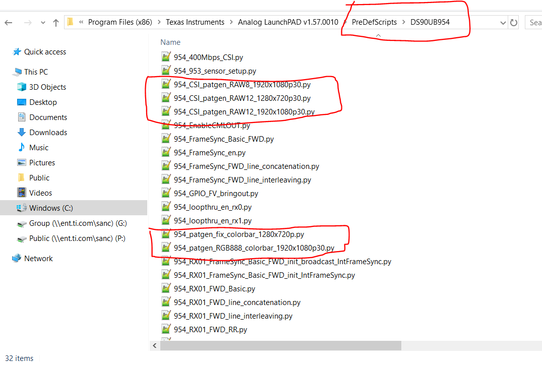
Below is my register settings:
## PatternGenerationOn954.py
#
# RAW10 1920*1080
#
# I2C_ADDR 0x7A
#
#
## # # # # # # ##
# CSI sel and CSI enable
i2c_write 8 0x7A 0x32 0x01 0x1 0x1
usleep 10000
i2c_write 8 0x7A 0x33 0x01 0x1 0x1 # Enable CSI continuous clock mode
usleep 10000
# enable pat gen
i2c_write 8 0x7A 0xB0 0x00 0x1 0x1
usleep 10000
i2c_write 8 0x7A 0xB1 0x01 0x1 0x1
usleep 10000
i2c_write 8 0x7A 0xB2 0x01 0x1 0x1 #enable pattern generator
usleep 10000
i2c_write 8 0x7A 0xB1 0x02 0x1 0x1
usleep 10000
i2c_write 8 0x7A 0xB2 0x35 0x1 0x1 #Color Bar pattern ,8 color bars block,Block size of 5 Byte
usleep 10000
i2c_write 8 0x7A 0xB1 0x03 0x1 0x1
usleep 10000
i2c_write 8 0x7A 0xB2 0x2B 0x1 0x1 #CSI Data Identifier ( 0x24 = RGB888 0x2C = RAW12 0x2B = RAW10)
usleep 10000
i2c_write 8 0x7A 0xB1 0x04 0x1 0x1
usleep 10000
i2c_write 8 0x7A 0xB2 0x09 0x1 0x1 #line size (15:8) 1920*10/8=2400=0x960
usleep 10000
i2c_write 8 0x7A 0xB1 0x05 0x1 0x1
usleep 10000
i2c_write 8 0x7A 0xB2 0x60 0x1 0x1 #line size (7:0) 1920*10/8=2400=0x960
usleep 10000
i2c_write 8 0x7A 0xB1 0x06 0x1 0x1
usleep 10000
i2c_write 8 0x7A 0xB2 0x01 0x1 0x1 #bar size (15:8) 1920*10/8/8=300=0x12C
usleep 10000
i2c_write 8 0x7A 0xB1 0x07 0x1 0x1
usleep 10000
i2c_write 8 0x7A 0xB2 0x2C 0x1 0x1 #bar size (7:0) 1920*10/8/8=300=0x12C
usleep 10000
i2c_write 8 0x7A 0xB1 0x08 0x1 0x1
usleep 10000
i2c_write 8 0x7A 0xB2 0x04 0x1 0x1 #active lines per frame (15:8) 1080
usleep 10000
i2c_write 8 0x7A 0xB1 0x09 0x1 0x1
usleep 10000
i2c_write 8 0x7A 0xB2 0x38 0x1 0x1 #active lines per frame (7:0) 1080
usleep 10000
i2c_write 8 0x7A 0xB1 0x0a 0x1 0x1
usleep 10000
i2c_write 8 0x7A 0xB2 0x04 0x1 0x1 #total lines per frame (15:8) 1125
usleep 10000
i2c_write 8 0x7A 0xB1 0x0b 0x1 0x1
usleep 10000
i2c_write 8 0x7A 0xB2 0x65 0x1 0x1 #total lines per frame (7:0) 1125
usleep 10000
i2c_write 8 0x7A 0xB1 0x0c 0x1 0x1
usleep 10000
i2c_write 8 0x7A 0xB2 0x0B 0x1 0x1 #line period (15:8) 1/(30*1125*10ns)=2963
usleep 10000
i2c_write 8 0x7A 0xB1 0x0d 0x1 0x1
usleep 10000
i2c_write 8 0x7A 0xB2 0x93 0x1 0x1 #line period (7:0) 1/(30*1125*10ns)=2963
usleep 10000
i2c_write 8 0x7A 0xB1 0x0e 0x1 0x1
usleep 10000
i2c_write 8 0x7A 0xB2 0x21 0x1 0x1 #vertical back porch 33
usleep 10000
i2c_write 8 0x7A 0xB1 0x0f 0x1 0x1
usleep 10000
i2c_write 8 0x7A 0xB2 0x0a 0x1 0x1 #vertical front porch 10
usleep 10000
usleep 10000
i2c_write 8 0x7A 0xB1 0x10 0x1 0x1
usleep 10000
i2c_write 8 0x7A 0xB2 0xff 0x1 0x1 #1st byte of fixed color
usleep 10000
i2c_write 8 0x7A 0xB1 0x11 0x1 0x1
usleep 10000
i2c_write 8 0x7A 0xB2 0x00 0x1 0x1 #2nd byte of fixed color
usleep 10000
i2c_write 8 0x7A 0xB1 0x12 0x1 0x1
usleep 10000
i2c_write 8 0x7A 0xB2 0xff 0x1 0x1 #3rd byte of fixed color
usleep 10000
i2c_write 8 0x7A 0xB1 0x13 0x1 0x1
usleep 10000
i2c_write 8 0x7A 0xB2 0x00 0x1 0x1 #4th byte of fixed color
usleep 10000
i2c_write 8 0x7A 0xB1 0x14 0x1 0x1
usleep 10000
i2c_write 8 0x7A 0xB2 0xff 0x1 0x1 #5th byte of fixed color
usleep 10000
i2c_write 8 0x7A 0xB1 0x15 0x1 0x1
usleep 10000
i2c_write 8 0x7A 0xB2 0x00 0x1 0x1 #6th byte of fixed color
usleep 10000
i2c_write 8 0x7A 0xB1 0x16 0x1 0x1
usleep 10000
i2c_write 8 0x7A 0xB2 0xff 0x1 0x1 #7th byte of fixed color
usleep 10000
i2c_write 8 0x7A 0xB1 0x17 0x1 0x1
usleep 10000
i2c_write 8 0x7A 0xB2 0x00 0x1 0x1 #8th byte of fixed color
usleep 10000
Best Regards.