This thread has been locked.

If you have a related question, please click the "Ask a related question" button in the top right corner. The newly created question will be automatically linked to this question.

DP83822IF: Can DP83822IF be used when there's only one fiber wire connected

Part Number: DP83822IF

Hi team,

My customer is using DP83822IF to do fiber communication in a substation protection project. Normally, there are two pairs of fiber wires connected to the PHY and one pair is TX and the other pair is RX. But there is a special use case claimed in the National Standard that the PHY must correctly receive the data package when there's only one pair fiber wire connected the PHY.

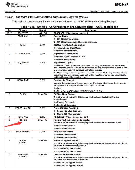
In our DP83849 datasheet, this function can be realized by configuring below register. But in DP83822IF datasheet, we didn't find the similar register. Could you please help check how to realize this configuration in DP83822IF? Thanks.
  

Best regards,

Wayne

  • Hi Wayne,

    We do have those bits in a internal register. Bits [6:5] of register 0x40 can be used to disable Far End Fault. Set them both to '1'to disable FEF. This registers is not in the datasheet, I would advise first reading the register and then changing only bits [6:5].

    Other option is to assert signal detect using a external pull resistor. This will mimic a good link even when 1 channel is used.

    -Regards
    Aniruddha
  • Hi Aniruddha,

    Thanks for your advice. We tried to adjust the 0x40 register as your recommendation. When we read out the 0x40 register, the value is 0xC11D. Then we changed it to 0xC17D to set Bits [6:5] to both 1. Then we connected only one pair fiber cable to the PHY to do the test. The phenomenon is as below:

    1. When we use the single pair fiber cable to receive data package, it works well.
    2. When we use the single pair fiber cable to send data package, the 'Link status' LED on the partner board which is on the other side of the fiber cable is ON. This means the link between 83822IF and the partner board is OK. But the 83822IF cannot send data package out. ( In the last thread, I said customer requires 83822IF must correctly receive the data package when there's only one pair fiber cable connected. But today, customer told me 83822IF must also can correctly send data package when there's only one pair fiber cable connected)

    So I just want to check with you:

    1. If the value 0xC11D read out from 0x40 register is the correct default value? Can you share the detailed description of every bit of 0x40 register?
    2. From the phenomenon above, it seems setting Bits[6:5] to both 1 cannot make 83822IF correctly send data package when there's only one pair fiber cable connected. So do you have any advice to force the PHY to send out data when there's only one pair fiber cable connected?
    3. For your second solution in the last thread, you mentioned we can 'assert signal detect using a external pull resistor '. I did't quite understand where to add the external pull resister. Can you explain more detail? where to add? pull up or pull down? what's the resistor value?

    Thanks.

    Best regards,
    Wayne
  • Hi wayne,

    The transmit requirement from customer is new, so I will recommend trying the Signal Detect method first. In Fiber mode, LED_1 can work as signal detect input pin. In normal Fiber Ethernet application, Signal Detect output of Fiber transceiver is connected to LED_1 pin of the PHY and PHY uses this input to check if signal is present on the Fiber Cable or not. In order to active Signal Detect feature, make sure that SD_EN is 1 as per strap table 11 in the datasheet. Signal Detect input is active high by default, so customer can connect a 2.2kohm pull up resistor between LED_1 and VDDIO.

    0x40 is a type of configuration register reserved for internal use. Bits[6:5] are the ones responsible for FEF. I can say that 0xC11D is the correct default value for register 0x40.

    -Regards
    Aniruddha
  • Hi Aniruddha,

    Thanks for your reply. We followed your advice as below:

    1. Make RX_ER pin floating to make it's bootstrap to MODE4 which means SD_EN=1

    2. We kept 0x0465 register bit 0 as default value which meas SD pin is Active HIGH

    3. We pull up SD pin to VDDIO to make the PHY thinks the link is OK.

    4. Read 0x40 register data out and write 0xC17D into it,

    After all the above configuration, 83822IF still cannot send data package out when there's only 1 pair fiber wire connected. So do you think if there's any configuration missing here? Is there any other register needs to be configured except for the FEF function? Thanks.

    Best regards,

    Wayne

  • Hi Wayne,

    If I understand the problem correctly, the link is up but there is not data communication. What is the mac interface? MII or RMII? Can you try enabling the loopback from register 0x16, you can try using digital loopback. This will help check MAC interface transmit connections.

    -Regards
    Aniruddha