This thread has been locked.

If you have a related question, please click the "Ask a related question" button in the top right corner. The newly created question will be automatically linked to this question.

DP83822HF: DP83822HF Can't communication issue

Part Number: DP83822HF
Other Parts Discussed in Thread: AM5728

Hi Team,

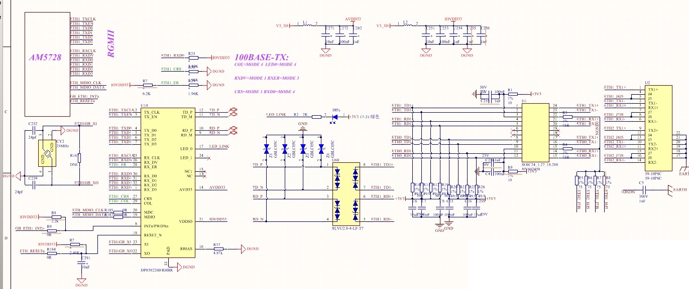
We penetrated our DP83822HF in new project in our customer, 4pcs/board. All DP83822HF are using RGMII interface and copper port. Debug is on-going, but now both link and communication failed, below is schematic and more information:

More information:

1. We can use MDIO interface to write registers and also read out registers from DP83822HF;

2. AVDD33 and DVDD33 are all 3.3V;

3. VBIAS is about 0.96V;

4. We measured that input reference is 25MHz;

5. TX_CLK is 25MHz but RX_CLK is 2.5MHz!!!!

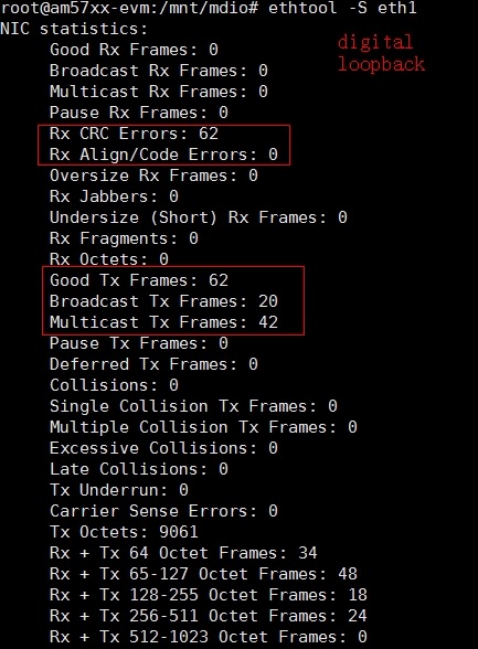
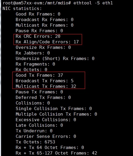
6. Tried MII Loopback, link status is 0, seems failed. Also tried Digital Loopback, link status is  and TXD seems output some data to PHY, however CRC check has  many errors;

7. Tried to use RGMII RX/TX Clock shift as well(Tried all 00, 01, 10, 11), still can't work, communication failure;

8. Below is registers value read out from DP83822HF:

Since project schedule is urgent, need team's great support on this, thanks a lot!

Best regards,

Sulyn


  • Hi Sulyn,

    Maybe the PHY is not getting strapped in the correct modes. Can you read back register 0x00, 0x01, 0x04, 0x09, 0x10, 0x17, 0x19, 0x467, and 0x468 and send the status?

    -Regards
    Aniruddha
  • HI Aniruddha,

    Thanks for the support, you can find the value for these registers as below:

       0x00 0x3100

       0x01 0x7849

       0x04 0x01e1

       0x09 0x0000

       0x10 0x0002

       0x17 0x0241

       0x19 0x8003

       0x467 0x3e03

       0x468 0x0000

    Not sure if these is any problem for these registers value?

    Best regards,

    Sulyn

  • HI Aniruddha and team,

    Would you pls help check this, as I'm on site at customer side for this urgent debug, would you pls help look into this.

    Best regards,

    Sulyn

  • Team,
    If based on above information and condition, if MII loopback failed, can you help analysis the possible reason for this?


    Best regards,
    Sulyn
  • Hi Aniruddha,

    Sorry that can't reach you by phone, as it's urgent and now communication still failed and we tried loopback function, also failed! Today based on the test, got more information, showed as below:

    Now for loopback:

    1. MII loopback, failed, the register 0x01's bit 2, link status didn't change, still 0. So Mac can't send data to PHY;

    2. Digital loopback, the register 0x01's bit 2, link status change from 0 to 1, but we got below errors:

    3. Analog loopback, the register 0x01's bit 2, change from 0 to 1, but we also got below errors:

    Would you pls help further check these information together with the information I posted in last serial post, now debug is urgent, if this issue not resolved, we may lost this opportunity. Thanks for your support.

    Best regards,

    Sulyn

  • Team,

    Any expert can help check this issue? Already pending for a while and customer is pushing for the support. Thanks

    Best regards,

    Sulyn

  • Hi Sulyn,

    Apologies for the delayed reply. For the MAC side, please check with customer that RGMII traces are length matched. All RGMII TX data lines need to be matched to RGMII TX Clock. All RGMII RX Lines need to be length matched to RGMII RX clock. But the TX lines need not be length matched to RX Lines. Is there RGMII internal delay in AM5728? If yes, what is that delay? DP83822 has internal delay of 3.5ns. By default, RGMII TX delay is enabled and RGMII RX delay is disabled. 

    For the Cable side, can you confirm that Bob Smith termination is implemented between magnetics and RJ-45. Magnetics center taps need to be directly pulled to AVDD voltage, on the schematics I see R1 and R9 as 10ohm resistors. Can you ask customer to replace 10ohm resistors with 0ohm. Also PHY is supplied with 'AVDD33' voltage rail but center tap is connected to '+3V3' voltage rail. Where is the '+3V3' voltage rail getting derived from? 

    Lasltly, can you ask customer to share the oscilloscope image of the waveform on MDI channel (TD+/- and RD+/- pins)?

    -Regards

    Aniruddha