This thread has been locked.

If you have a related question, please click the "Ask a related question" button in the top right corner. The newly created question will be automatically linked to this question.

TUSB217-Q1: TUSB213 to TUSB217

Part Number: TUSB217-Q1
Other Parts Discussed in Thread: TUSB213, TUSB217,

Hi Sirs,

Sorry to bother you.

We would like to know 

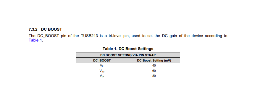
1. What is the voltage set by the AC/DC boost setting parameters for each step?

TUSB213 show as below

2. We set 217 AC: F0 DC: 00 213 AC: 78 DC: 08, why is resevre bit set this way?

3. Continue to point 2, can the 217 set value be applied to 213?

4. Rx SEN function? What value do we want to set?

Datasheet suggest to pull high?

  • Hi Sirs,
    One more question.
    Is possible use I2C command to check the ID (between 213 or 217)?
    If no ,have other way to use I2C check the IC is 213 or 217?
  • Hi,

    1. Please see the DC Boost section of Table 6.5 Electrical Characteristics in TUSB213 datasheet for Vil,Vim,Vih.

    2. Could you explain your question? I am not sure what you are asking.

    3. If I understand your questions no, the settings or TUSB217 and TUSB213 are different.

    4. Rx Sen should be pulled high for high loss channels.

    5. There is no ID in TUSB213 or TUSB217 that will allow you to tell them apart. Keep in mind that you should not have two devices with the same I2C address on the I2C bus.
  • Hi Sirs,

    1. Please see the DC Boost section of Table 6.5 Electrical Characteristics in TUSB213 datasheet for Vil,Vim,Vih.

    So, you mean we could refer TUSB213  Vil,Vim,Vih even we use TUSB217?

    2. Could you explain your question? I am not sure what you are asking. 

    We setting TUSB217 AC:F0 DC:00 TUSB213 AC:78 DC:08,We would like to know why resevre bit need this seeting??

    3. If I understand your questions no, the settings or TUSB217 and TUSB213 are different.

    4. Rx Sen should be pulled high for high loss channels.

    5. There is no ID in TUSB213 or TUSB217 that will allow you to tell them apart. Keep in mind that you should not have two devices with the same I2C address on the I2C bus.

    So if use TUSB213 and TUSB217 on the same board, we couldn't use ID to check who is TUSB213 and who is TUSB217, right?

  • Hi,

    1. No the for TUSB217-Q1 please see section 8.2 Typical Application and Table 8 -10 for example on configuring BOOST and RX SEN pins.

    2. I am not sure what you mean by reserve bit, could you explain?

    5. This is correct but as I mentioned before you should not have two devices with the same I2C address on the same bus as this could cause bus contention. One solution to this is that one device should be used in GPIO mode and the other should be I2C.
  • Hi Sirs,
    Thanks for your reply
    About Q1. We would lile to know level 0 =??mV, level 1= ?? mV....
  • Hi,

    TUSB217-Q1 BOOST pin uses a precise resistance to determine its settings, it is not voltage based. Voltage levels for RX_SEN pin are listed in 6.5 Electrical Characteristics table in TUSB217-Q1 datasheet. Please refer to the 6.5 Electrical Characteristics table of TI datasheets as the Vih and Vil limit (and similar data) are more than likely specified here.
  • Hi Sirs,

    Thanks for your reply,

    So TUSB217 didn't have DC Boost Settings mV value such like TUSB213, right?

    Actually we eye pattern fail on TUSB213 but pass on TUSB217, so we would like to know what different between them.

    Thanks!!

  • Hi,

    Correct, the main difference TUSB217-Q1 has different boosting values DC and AC that are not equal TUSB213. What is your test setup and results? How is the eye failing for the TUSB213 setup?
  • Hi Sirs,

    Not get end customer any feedback.

    As i know 217 is test passed on their device but some of 213 didn't.

    That why they would like to know different between them.

    I'll close this topic.

    Thanks!!