This thread has been locked.

If you have a related question, please click the "Ask a related question" button in the top right corner. The newly created question will be automatically linked to this question.

TPS65987D: USB PD Controller damaged (Low impedance VBUS to GND)

Part Number: TPS65987D

Hi, we are using the TPS65987DDH on a BMS application (Power Bank). 

It is supposed to operate as a DRP, and the TI Application Customization Tool has been used to prepare a configuration. 

The USB PD Controller schematic is as follows:

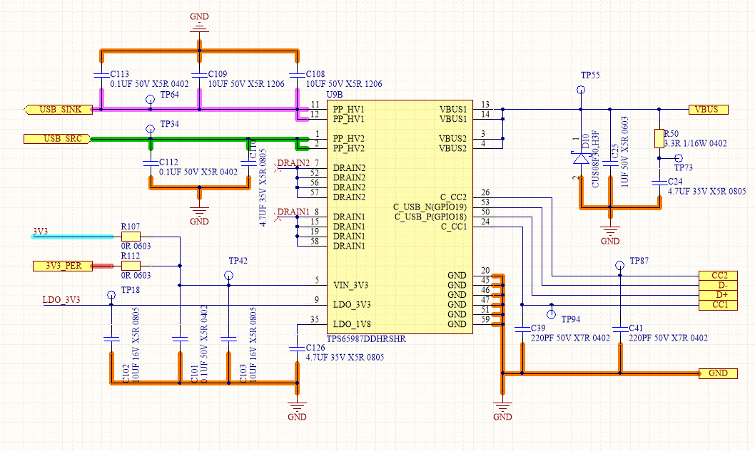
^ R112 is not populated.

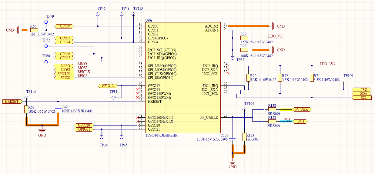
^ R123, R128 not populated.

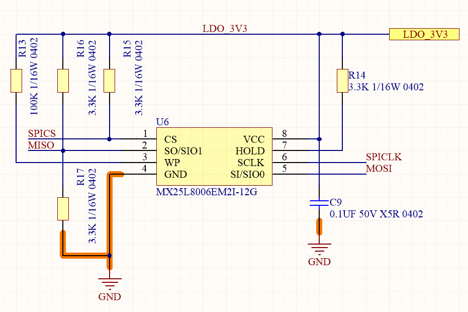
^ R17 not populated.

After usage on the PD Controller to turn on a non inverting buck boost converter (charger for the power bank) on the USB_SINK line, there are random failures that we are observing. One common failure that is observed is there is low impedance between VBUS and GND (~ 6 ohm). In addition to this, the low voltage circuitry on the PD Controller also fails (Excess current drawn from 3V3 as well and PD Controller turning hot) > 80 degree C. We are observing the highest voltage due to transients on the USB_SINK, USB_SRC, VBUS line is not higher than 20.8V, which is still acceptable under the operating limit ( < 22V). Hot plugging transients with a 2 meter USB cable are < 22V.

1. What can be the possible causes of having these failures? Anyone experienced this before?

2. Can the FMEA for the PD Controller be shared?

3. The PD Sleep Configuration is currently as per 1000 msec. What is the sequencing followed for the power path opening when the USB PD goes to sleep from idle?

Thank you

  • Hi Rachit,

    I would suggest measuring the current going through the power path of the PD controller. Please keep in mind that the PD controller will not limit current when the power path is being used as a sink. These failures typically occur if the VBUS/PPHV voltage spec is violated or if the current drawn is greater than 5A.

    The PD controller will only go to sleep mode if there is nothing connected on the Type-C port and there is no I2C communication either.

    Thanks,
    Eric
  • Hi Eric,

    Thanks for the inputs. We suspected the same (over-voltage) and found the case of over-voltage on the lines happening only under specific circumstances on the system which was difficult to reproduce.

    On sleep mode: This case is noted, however we are particularly interested in the opening sequence of power path when the USB PD goes to sleep from idle. Do you have any timings/waveforms that have been benchmarked?

  • Hi Rachit,

    All available power path measurements are available in the following app note: www.ti.com/.../slva994.pdf

    Thanks,
    Eric