This thread has been locked.

If you have a related question, please click the "Ask a related question" button in the top right corner. The newly created question will be automatically linked to this question.

TCAN1043-Q1: CAN bus design architecture question

Part Number: TCAN1043-Q1

Hi Sir,

Recently my customer is asking about the CAN bus design architecture as below diagram

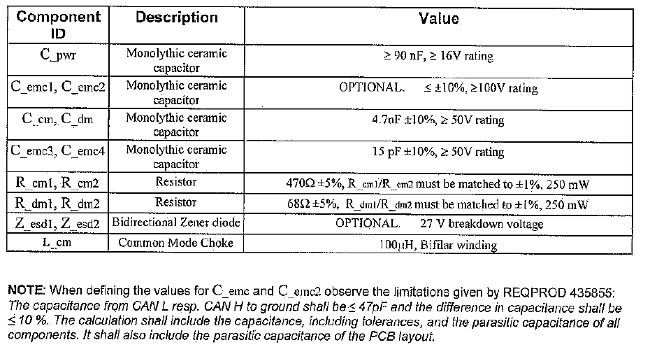
In their current design, it need R_dm1, R_dm2(termination resistors),C_dm.Cemc3,4,

but they just found some of the design, there is no R_CM 1 , R_CM2 and C_cm, could you please help to explain the reasons?

If the R_CM 1 , R_CM2 and C_cm are no need, should we reserve these parts and what’s the main function for these ?

  • Hi Anne,

    From what I can tell, it looks like the (dm) and (cm) components both serve as termination schemes for the transceiver. Since there is a common-mode-choke on the board (L_cm), it looks like maybe the design is allowing the termination to be populated on either side of the choke. So you could choose to populate the (dm) components and leave the (cm) components unpopulated, or you could choose the reverse. In either case, I have never seen termination resistors and capacitors populated on both sides of a choke at the same time, so one set of them should be left unpopulated on the board.
    The typical case is to implement termination as close to the transceiver as possible. This helps keep the transmission line stub lengths effectively as short as possible from the termination. If you have any more information about the customer's specific use case that you think may be helpful here, please let me know. But normally we just see the R_dm1,2, C_dm, and C_emc3,4, Z_esd1,2 components populated with the choke.

    Does that make sense?

    Best Regards,
    Max Megee
    TI Transceiver Applications
  • Hi Max,

    Thanks for your feedback. However, we found out the value is different between Rcm, Rdm as attachment. If the situation like you mentioned, the value should be approximate the same (the terminal value is 120 ohm). Could you please help to check it is necessary to reverse the Rcm? Attached the value for each parts.   


    Louis

  • Thank you for the follow up with the values.  It helps me to get a better understanding of the circuit now.  

    It looks to me like the R_cm resistors may be for common mode evaluation of the device.  If a test voltage were placed on the node between R_cm1 and R_cm2, then the transceiver could be tested across its specified common mode voltage input range.  470 ohms is a plausible value for common-mode loading on the bus.  But I have only seen a circuit like this implemented in order to test the performance of a single device.  I have never seen it used in a real system once the device is evaluated.  So for an actual application with continuous CAN communication, I would depopulate that circuit.  

    You can see in our datasheet that we showcase a circuit like this in order to show how we specify the common mode performance.

    That is my best conjecture about the use of the R_cm components.  Does that make any sense in your use-case?  I think you should be able to remove the circuit.

    Best Regards,

    Max Megee