This thread has been locked.

If you have a related question, please click the "Ask a related question" button in the top right corner. The newly created question will be automatically linked to this question.

TPS65987D: Initial configuration setup

Part Number: TPS65987D
Other Parts Discussed in Thread: TPS65987, TIDA-050014

Hi TI,

We have 'TPS65987-90 Evaluation Module' with us. Also we are using 'TPS65987DDHRSHR' in our system with external Flash.

We have to make USB type C port on our system to act as sink only (This port will take power from USB Type C adapter). We are not bothered about data communication through this port .

i) When we are connecting USB type C adapter to our system, the VBUS is coming out to be 0V. We checked this for following configurations:

SPI MISO R2/(R1+R2) Dead Battery Mode Device Configuration
0 0.4 0.48 BP_NoWait Configuration 3
0 0.3 0.38 BP_ECWait_Internal Infinite Wait
1 0.2 0.28 BP_WaitFor3V3_Internal Safe Configuration

We connected VIN_3V3 of TPS65987D (pin no.5) from external battery. LDO_3V3 and LDO_1V8 is generated from TPS65987D. There is nothing in Flash for now.

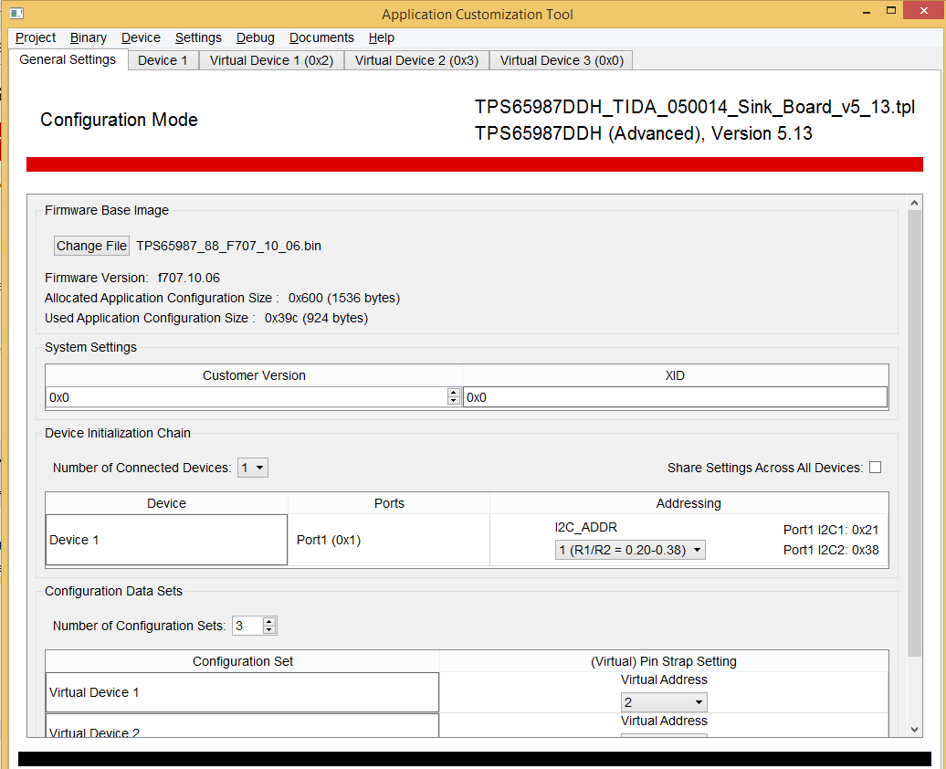
ii) When we connected the EVM,and opened TPS6598x Application-Customization Tool and gone to Debug mode, its just showing polling disconnected trying FTDI 0x38 or 0x20.

iii) As there is no FTDI chip on our system, we connected our Flash in place of EVM flash and connected the evm to PC to make use of FTDI chip of EVM. Then in TPS6598x Application-Customization Tool we gone to binary---->Flash from binary file then selected "TPS65987_88_F707_10_04" file and OK. Then it showed FLASH erasing, programming but verification is failed at the end.

iv) Kindly guide me where am I going wrong? or what is procedure to run the TPS65987D IC properly as in our case even default 5V is also not coming VBUS line.

Please find attached our schematic of TPS65987D part for reference.

Thanks for reading.

BR.

  • Hello Sameer,

    MISO should not be pulled low. The TPS65987D will see this and not receive the patch bundle from the SPI flash. That could be the problem you are seeing is that the configuration is never loaded into our part.

    As far as the FTDI not working properly, I would recommend removing and re-downloading the drivers for FTDI to see if that fixes the issue.
  • Hi Adam,
    Thanks for reply...
    I connected EVM to other computer,so it's showing connection....may be driver issue was there as you said.
    I) Now I pulled MISO high and as I said earlier in point three above to make use of FTDI chip of EVM, I made switch S3 of EVM off. So SPI and I2C Lines from FTDI chip are not going to TPS65987D of EVM. These lines I connected to our system TPD65987D and Flash.
    II) Now I connected EVM to PC,so this time SPI scanning was successful but it's showing 'polling disconnected trying FTDI 0x38 or 0x20'. so there is some problem with I2C.
    But as SPI is OK,from customization tool, I gone to BINARY---->FLASH FROM BINARY---->I selected "TPS65987_88_F707_10_04" and OK. This is programmed and verified successfully. Then I restarted and checked output voltage at VBUS but it was 0 V.
    III) Now,I gone to DEVICE---->FLASHED THE FIRMWARE OF EVM...This was also successful. But again it is showing 0 V.
    And it's not even showing legacy voltage of 5V.
    Kindly guide on this...


    I guess there are two EVMs of TPD65987D
    a)TPS65987-90EVM
    b)TPS65987DEVM(only for single device)
    We have (a) type. But in schematic of (b) type,there is one overvoltage protection and ESD device (U2) to which both CC pins from the type C connector are connected...and it's doing some Rd resistance work...but we have not used such IC as there was nothing like that in our EVM ( (a) type).
    Does it matter or Rd is taken care of internally.

    Thanks.
    BR.
  • Any update on this plz.

    BR.

  • Hello Sameer,

    If you are able to successfully configure the device, then the problem lies either with your application configuration that you are programming onto your system, or your implementation of the TPS65987D on your system. Have you flashed your sink configuration onto a TPS65987DEVM? Do you see it working as expected?
  • Hello Adam,

    Thanks for reply.

    I found one design from TI which has similar application as ours & that design is "TIDA-050014". In application customization tool, I selected Project---->New project---->TPS65987DDH---->TIDA-050014 Sink board.  It shows like below

    Now I gone to Binary---->Save binary....Saved low region file of this project.

    Then I connected my EVM "TPS65987-90 Evaluation Module" and flashed this saved binary to EVM. But when I connected type C adapter to EVM it is showing 5V voltage only.(Then I did 're-Flash EVM firmware' to get back to initial config). Can I get the binary or project file of TIDA-050014 which can give 20 V at VBUS in EVM so that I can test that in EVM as well as my board?

    I found similar thread with same requirement. Its link is http://e2e.ti.com/support/interface/f/138/p/752130/2785194#2785194?jktype=e2e .

    Kindly help.

    BR.

  • Hello,

    Thank you for the further explanation. There are two issues with what you described. The first is when creating a bincary image you intend to load onto the external flash. Your sequence is correct, but instead of clicking to save the low region of the project, click to save the full flash image. The low region is typically used when using an external EC to push the patch bundle while the full flash image is used for an external flash.

    The second issue is that the TIDA-050014 project uses the buttons populated on the PCB to change the sink capabilities advertised to a source charger. The default state of the TIDA-050014 is only 5V. Here is an excerpt from the user's manual, explaining how the pushbuttons work.

    "TIDA-050014 is designed to request four different PDO's depending on what the customer is wanting to
    test. 9V_PB_SINK, 15V_PB_SINK, and 20V_PB_SINK are connected to three individual GPIO pins on the
    TPS65987D. 5V_PB_SINK will be connected to HRESET. When the push buttons are not pressed, each
    of the GPIO's will be pulled low. Upon initial startup, each GPIO will be pulled low and the TPS65987D will
    go in its default state of requesting 5 V. When a push button is pressed, its corresponding GPIO will be
    pulled high, and then that sink voltage will be requested by the TPS65987D.
    For example, a USB Type-C PD source controller, capable of supplying up to 20 V, is connected to the
    TIDA-050014. The TIDA-050014 will go into its default state, and request 5 V from the source controller. If
    the user wants the sink voltage to change to 20 V, they would then press the pushbutton labeled "20 V".
    This will pull 20V_PB_SINK and it's corresponding GPIO high. The TPS65987D would then request a 20
    V PDO from the source controller, and the voltage on VBUS would then rise to 20 V. If they wish to return
    back to 5 V, press the button labeled "5 V". This will pull 5V_PB_SINK and HRESET high, and the
    TPD65987D will reset. When the TPS65987D comes back on, it will then request it's default voltage of 5
    V."

    I would recommend using one of the default UFP templates to make sure that your setup is capable of sinking a high voltage contract, and then from there, you can begin to port over different features you valued from the TIDA-050014 template.
  • Dear Adam,

    The main problem we are facing is, not even default 5V is coming on the VBUS of our type C connector. Even if we connect USB cable from computer to our board , 5V is not coming. TPS65987D comes with some default settings,configuration in flash is one thing but Legacy 5 V can always come. You have seen our schematic also. What changes you said I corrected them in schematic. Still problem persists.

    What is  solution or troubleshooting for this?

    BR. 

  • Dear Adam,

    We found the mistake in our schematic design. As given in datasheet that pin no.57 & 58 are thermal pads, we directly connected them to ground which is wrong. As though they are thermal pads but they should not be connected to ground. That's why even 5 V is not coming. Now after resolving this issue,I will get back to you if something else is needed.

    BR.