This thread has been locked.

If you have a related question, please click the "Ask a related question" button in the top right corner. The newly created question will be automatically linked to this question.

SN65LBC184: failsafe resistors

Part Number: SN65LBC184
Other Parts Discussed in Thread: THVD1419

Hi Sirs,

Sorry to bother you .

Below Fig.1 is our SN65LBC184D circuit.

We are confused on the resistance of failsafe resistors.


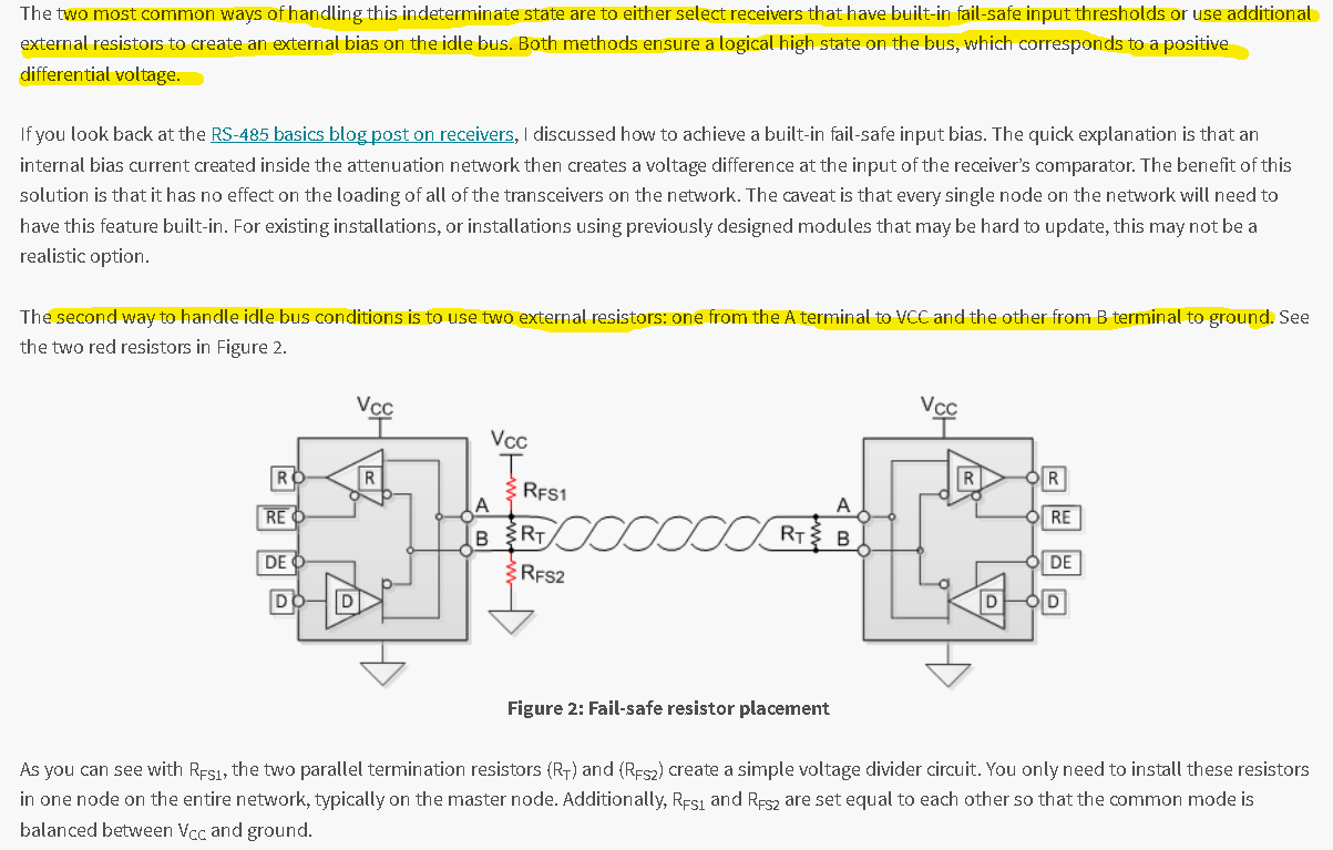
According to TI application report as Fig.2,

the failsafe resistors should be 600 ohm.

Can you please check it?

We would like to know  how to read RS485 waveform as Fig.3?

Fig.1

SN65LBC184D circuit

Fig.2

application report from TI

Fig.3
RS485 waveform
Ch1: RS485+
Ch4: RS485-
CHM: CH1-CH4


  • Hi Shu-Cheng,

    The transceiver itself does not require specific failsafe resistor values; this is a system-level design consideration. You can read more about the impact of the resistor values in this blog:

    e2e.ti.com/.../rs-485-basics-two-ways-to-fail-safe-bias-your-network

    On the screenshot, it looks like the "D" input to the transceiver may be held a low level while data toggles on the "DE" input - is this correct? I mention this because based on the schematic I would expect a small positive differential output (due to the external resistors) whenever all transceivers on the bus are disabled and a larger (~2 V) positive or negative differential output when a transceiver is enabled and driving high or low.

    Regards,
    Max
  • Hi Sirs,

    Thanks for your reply

    You wrote The transceiver itself does not require specific failsafe resistor values; this is a system-level design consideration.

    Do you mean SN65LBC184D built in open circuit failsafe receiver design and did not need external failsafe resistors?

    Can you explain more detail about this?


    According blog you forward https://e2e.ti.com/blogs_/b/industrial_strength/archive/2016/12/06/rs-485-basics-two-ways-to-fail-safe-bias-your-network ,

    If the transceiver did not built-in failsafe input threshold, the alternative way is to use additional resistors to create an external bias on the idle bus.

    Thanks!

  • Hi Sirs,

    Sorry to pushed, have any update on this case?

    Please check if SN65LBC184D has built-in failsafe circuitry includes open-circuit, short-circuit and idle-bus failsafe?


    Btw,

    Is there any doc or video to guide us how to check RS485 waveform?

    Please advise,

    Thanks!!

  • Hi Shu-Cheng,

    Sorry for the delay - I was out of the office yesterday, Yes, SN65LBC184D has internal failsafe biasing which is capable of detecting open circuits and idle buses. The implementation is shown in Figure 14 of the datasheet; note that the A line has a 12-uA pull-up current source and the B line has a 12-uA pull-down current source. This implementation is not capable of detecting short-circuit conditions, though. Also note that in most cases internal failsafe is designed to apply to just that transceiver's node and wouldn't necessarily enable failsafe protection on every other node in the network like external failsafe biasing would.

    You may want to look into a newer device like THVD1419. It improves upon the surge immunity of the older SN65LBC184 device and has an internal failsafe implementation capable of detected shorted-bus conditions as well.

    Max