This thread has been locked.

If you have a related question, please click the "Ask a related question" button in the top right corner. The newly created question will be automatically linked to this question.

HD3SS3220:HD3SS3220不能正常工作的问题

Part Number: HD3SS3220

I need help
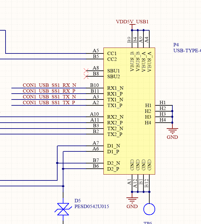
I chose the HD3SS3220 and HD3S3212 chips for the USB-TYPE-C interface design. I found problems during the debugging process. The phenomenon is that USB 3.0 cannot be recognized, only usb2.0 can be recognized, and it is the same under win10 and linux. My question is as follows:
Linux HD3SS3220 need to be driven by the driver, if not, please help me check the error in the schematic. (I have tried both DFP and UFP modes, and I can't recognize USB3.0)

  • This is the schematic of my design. I designed two schemes, one is DRP mode, the ID line is responsible for external power supply control; the other is UFP mode, I designed it with reference to datasheet, and did not fully comply with UFP/UDP reference. Design. I need an engineer to help me point out the mistakes in the design. If the error of the resistance position welding is well solved, if not, I think I need to redesign the schematic, and I need the engineer to provide some suggestions for what I need to repair.1.HD3SS3220.pdf

  • Would you please attached the schematic to this thread?

    Thanks
    David
  • 1. Are you seeing the issue with both DRP and UFP mode design?
    2. DIR, OUT1/2, VCON_FAULT, ID, INT_N/OUT3 pins are open drain outputs, they need to have 200k pullup on these pins
    3. Why use 10M on CURRENT_MODE pin?
    4. Are you having USB connectors on both side of HD3SS3220?

    Thanks
    David
  • I have read some questions about HD3SS3220 in the forum. I want to talk about my questions and debugging for DFP mode.
    My board is now connected to win10 and linux can not recognize USB3.0
    Master device
    I designed the DFP mode without reverse design of the RX and TX of the master device. That is to say, the TX connection of the master device is connected to the TX3 and RX connections of the HD3SS3220, but the TX and RX are used in the reference project. Exchange, two forums
    2. From the device side
    The RX and TX signals are not reversed. I designed the DFP mode in the datasheet and exchanged the polarity of the TX1/RX1 pins. But this is confirmed in the datasheet and does not affect the chip operation. In the slave The polarity of the A2/A3 pin is reversed. This is different from the official schematic. I also found some responses in the forum.
    e2e.ti.com/.../661914
    e2e.ti.com/.../702551
    3. Series capacitor
    I placed the position of the series capacitor reserved on the TX of the master device. The TX1 signal design error from the device side is not reserved, but I added a common mode inductor on the signal line. Here I can change it to a series capacitor. Do I need to modify it?

    According to your reply, I have modified the relevant pull-up resistors and resistance values. I found in other forum questions.
  • This is the main port type-a


    This is slave port type-c

    I have added a pull-up resistor in the corresponding position as you said, but HD3SS3220 is not working now, I am troubleshooting the reason, I hope to give me some good suggestions,

    Regards,

    Miracleswt

  • I connected HD3SS3220 through I2C and found that the I2C register can be read and written normally. When I write 0x20 to register 0x0A, the write is successful, but the chip reading is not normal. I measured the CC pin and found that when the CC tube When the foot detects the peripheral, the level is pulled to 0.38V. This phenomenon occurs in CC1/2. I understand that the chip detects the peripheral. I now suspect that the connection method is wrong when I design the TX/RX signal. I can't get the peripherals, I don't know if you can help me confirm.
    My USB-TYPE-A is directly connected to the computer. The USB-TYPE-C interface is directly connected to the peripheral. Is it because I have reversed the transmission or transmission during the design?

    Regards

    Miracleswt
  • Miracleswt

    For the Type A, is this a connector or a plug? Are you connected directly into the computer or connected to the computer through a USB3 cable? If you are connected through a cable, then the current TX/RX implementation is not correct.

    I also attached the expected CC voltage when connected for the default USB Type-C current advertisement. The CC connection is separate from the SuperSpeed connection. If you are not seeing the correct voltage, then I would check the CC connection. 

    For I2C, please read the register 0x00h. This is the DEV_ID which is a read-only register. This is a good register to check for I2C connection. If you are able to read back the value consistently, then I2C is working properly. If not, then you may need to change pullup resistor on the I2C bus.

    Thanks

    David

  • I listened to your suggestion, changed the send and receive signal on the type-c side, and now I can find the device, but I have encountered other problems. When the device is plugged in, CC1/2 detection is no problem, but only TX2/ RX2 communication is normal, TX1/RX1 communication is not normal, even if the direction of sending and receiving is changed, the device cannot be identified.

  • I measured the CC level. When I connected the corresponding data line, the level of the CC pin was kept at 0.37V. I queried the datasheet and found that this value conforms to the V (ac_cc_med) voltage range in DFP transmission mode. I followed you yesterday. Said cross-transmission line, then CC1 works fine, connected peripherals can be identified, but when I flip CC2, although the CC2 level is normal, but the peripherals can not be identified, I found I2C data, 0X09 this The value of the register is 0x30.I didn't find out what caused the value of this register to change. I don't know if the change of this register is related to the problem of not being able to identify the peripheral when connecting CC2. You need to confirm it for me.

    Regards

    Miracleswt
  • I think I found out what caused this problem. I have solved the DFP mode. Next I will start debugging UFP and DRP mode.
  • Miracleswt

    I will close the thread for now, you can re-open it by responding to it once you have new info.

    Thanks
    David