This thread has been locked.

If you have a related question, please click the "Ask a related question" button in the top right corner. The newly created question will be automatically linked to this question.

SN65DP159: about SN65DP159

Part Number: SN65DP159

hi dear supporting team,

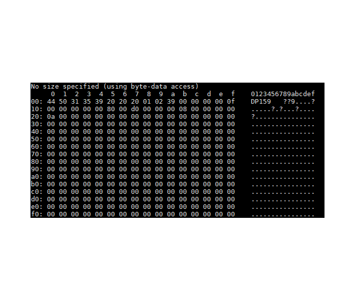
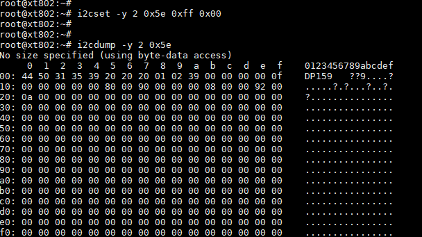
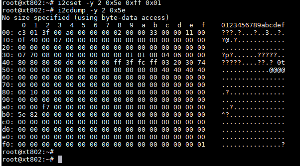
customer is using FPGA output HDMI signal to DP159, then SN159 send to TV, they will find there is sometimes the picture will disappear for around 2~3s, then recover, if they change DP159 to redriver mode, the issue will be solved.  what's the possible cause of this issue? The original setting which has issue is as below, they use default setting , and source is not using DDC. tks a lot!

  • Vera

    Would you please share their schematic and provide Page 1 register dump?

    What is the data rate out of the FPGA? Is it HDMI1.4 or HDMI2.0?

    One of the differences between retimer and redriver is that PLL is enabled in retimer mode, so you may want to check the input clock as the DP159 PLL needs to lock onto the input clock in the retimer mode.

    Thanks
    David

  • 1050.DP159.pdfhi David,

    the sch and dump register is as attached.

    the signal from FPGA is 1080p60, HDMI1.4.

    pls help double check whether there is anything unproper. I am asking them double check the ref clk as well. tks a lot!

  • hi David,

    the  dump register is as attached. I will send you the sch by email.

    the signal from FPGA is 1080p60, HDMI1.4.

    pls help double check whether there is anything unproper. I am asking them double check the ref clk as well. tks a lot!

  • Vera

    Does FPGA support clock stretching on the DDC bus?

    The register dump shows input clock is locked, but please still check the clock signal as I would like to know when the clock became valid.

    Can you also see if you set Page 0 Register 0x0Ch to the value of 0x6C, does it help?

    Thanks
    David

  • Vera"

      any update?

  • Hi Brian, David,

    sorry about the delay! customer is occupied by another task. waiting for the feedback now. tks for your support!

  • Hi Brian, David,

    Because FPGA is not using DDC, they are not sure whether it support clk stretching.  They used 500MHz Bw scope test the clk, when issue comes up, there is no big change at the amplitude.

       After setting Page 0 Register 0x0Ch to the value of 0x6C, the issue is still there.

     The issue seems only show in below situations:

    1. Only show on some kind of TV.

    2. Randomly show up, but once it show up, it will be cycly. The trigger condition seems related with plug, or reboot the brd.

  • Vera

    How long does it take for the clock to be valid in terms of frequency, are they seeing a difference between working and non-working case?

    If FPGA does not support DDC, where does HDMI1_TX_SRC_SCL and HDMI1_TX_SRC_SDA connected? 

    When the display works after 2 or 3s, does it stay working?

    Thanks

    David

  • Hi David,

    the signal is keep sending to DP159, it will not be affect by HPD. after DP159 powering up, they will pull OE high, send signal to DP159.  It seems no changing in the clk frequency. if it is clk issue, is there any way to check whether it is locked in the DP159 register when issue show up?

    HDMI1_TX_SRC_SCL and HDMI1_TX_SRC_SDA is connected to FPGA, but the IP core did not handle DDC.

    Yes, most cases it will stay working.

    customer has two issues:

    1. in d/s, it mentioned Input termination voltage is 0.7V, but from one of the d/s plot, it is 2V, Which one is true?

    2. if CLK in VID(PP) exceed 1200mV, will it cause the issue? 

  • Vera

    1. Figure 5 is an example of input and output timing measurement, it is not an example to measure the Vterm.

    2. Max VID is 1.2V, so it will not be an issue with the DP159.

    During the 2 to 3s before the video is stabilized, please keep looping the I2C read, the register we need to look for is Page 1 register 0x00h for PLL lock and Page 1 register 0xB1h for clock detect.

    Thanks

    David

  • Hi David,

    Vera said I can contact you directly on E2E. Thank you for your prompt reply.

    For the 0x00 register, it sometimes changes from 0x02 to 0x03, and finally to 0xc3; sometimes it changes directly from 0x02 to 0xc3. I feel that this difference may be caused by  I2C access frequency limit. For the 0xb1 register, it goes directly from 0x02 to 0x82. And the values of these two registers will not change when the issue occurs.

    Does the Max VID refer to the peak-to-peak value? I have measured a negative single-ended voltage between the coupling capacitor and DP159. Is this acceptable for  DP159?

  • Value 0xC3 is expected value for register 0x00h and value 0x82 is expected value for register 0xB1h register.

    0xC3 indicates DP159 is in re-timer mode, and PLL has locked onto the clock. 0x82 indicates DP159 has detected the clock. If you are seeing these bits toggle during the 2 to 3s when there is no display, this could indicate the input clock to DP159 is not stable and became stable after 2 to 3s. Can you please probe the input clock during the 2 to 3s when there is no display?

    VID of max 1.2V is peak to peak voltage.

    Thanks

    David

  • Hi David,

    These two registers stays the same when there is no display.

    We measured the jitter of output clock and input clock of DP159. The max cycle to cycle jitter is about 50ps.

  • Zexiang:

        1.2v VID is single ended or differential? if single ended, it's too high.

  • Brian,

    The picture below is the voltage measured between the two AC-coupling capacitors by a 500M BW oscilloscope. The FPGA output IO type is BLVDS_25. We have no idea why the output swing is so large.

  • almost 4v, did you calibrate the scope/probe?

  • Yeah. We find there is large skew bwteen the output clock and the input clock when the 0x00 register in page 1 of DP159 is  0x3c.

  • ok,, did you fix the CLK VOD issue?