Hi Team,
1)
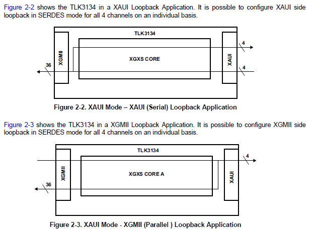
I believe "PLOOP pin = high" leads to Figure 2-3 and "SLOOP pin = high" leads to Figure 2-2 without setting registers.
Is my understanding correct?
-------------------------------------------------------------
2)
If the answer for 1) is yes, what is occured when "PLOOP pin = high" and "SLOOP pin = high"?
3)
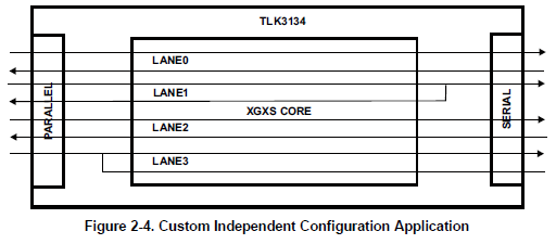
Could you tell me how to configure the following Figure 2-4?
-----------------------------------------------------------------------
Figure 2-4 shows the TLK3134 in a custom application example with mixed modes per Channel.
• Channel 1 in Parallel independent loopback mode
• Channel 3 in Serial independent loopback mode
• Channel 0 & 2 in independent channel transceiver mode
-----------------------------------------------------------------------
Best Regards,
Yaita
-
Ask a related question
What is a related question?A related question is a question created from another question. When the related question is created, it will be automatically linked to the original question.

