This thread has been locked.

If you have a related question, please click the "Ask a related question" button in the top right corner. The newly created question will be automatically linked to this question.

SN65DP159: SN65DP159 for AMD platform

Part Number: SN65DP159
Other Parts Discussed in Thread: TMDS181

Dear,


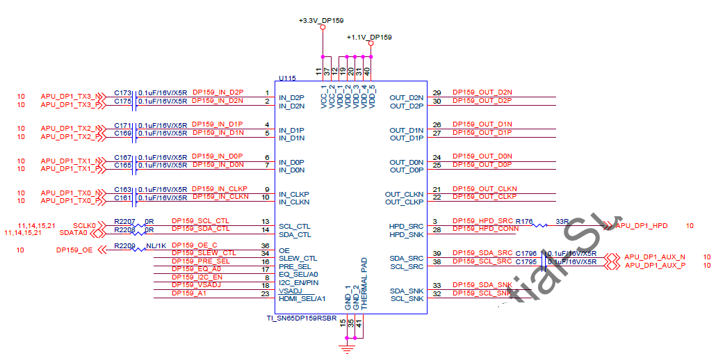
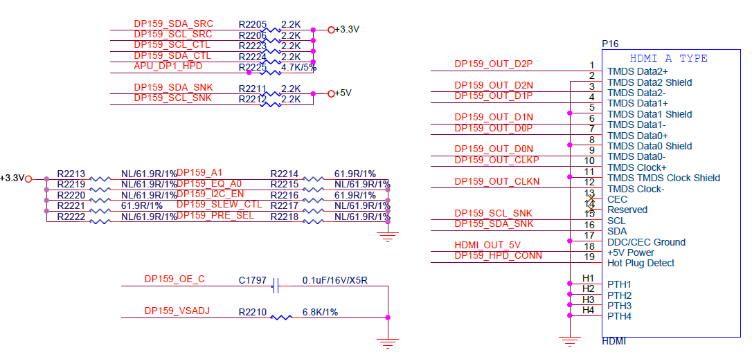
for AMD FP4 Type3 GX-215JJ ,PDG suggestion TI SN65DP159 solution , we need double confirm schematic and some question:

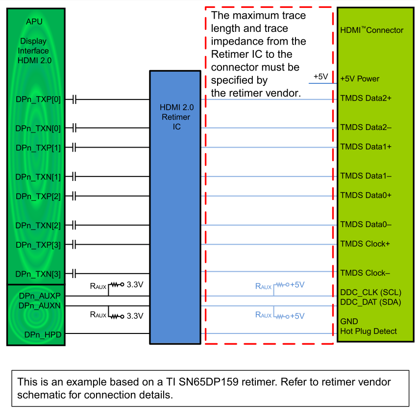
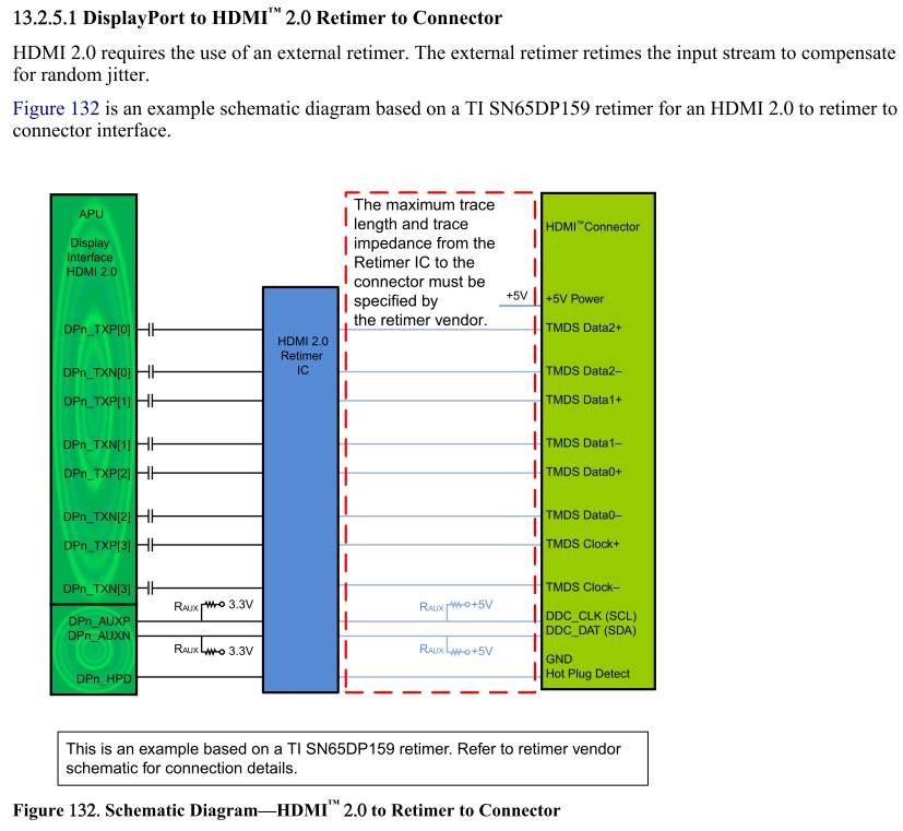
1. SNDP159 was can use HDMI to HDM? in our design is DP to HDMI but some question as below:


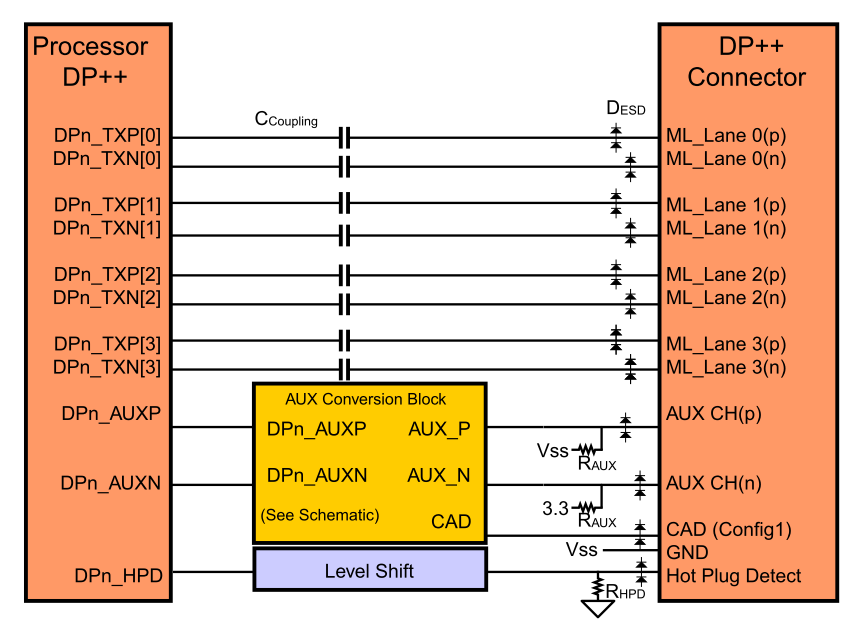
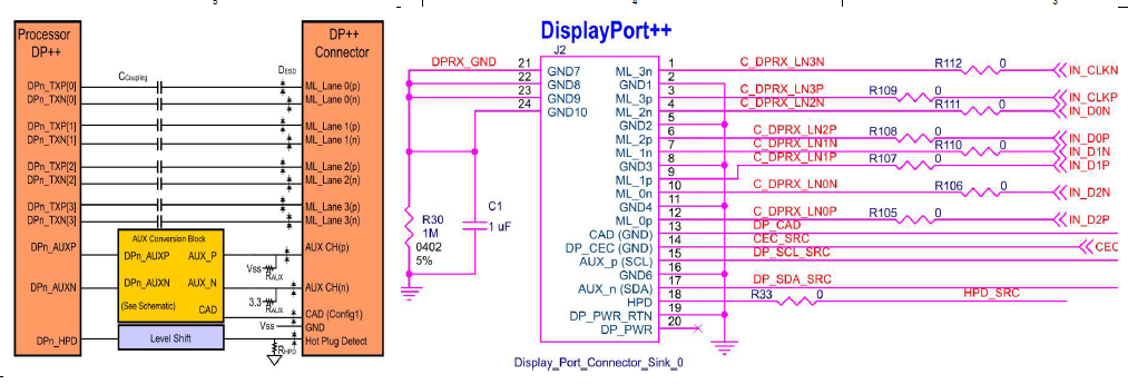
2.DP AUX Pin from CPU to SN65DP159 was need series cap?


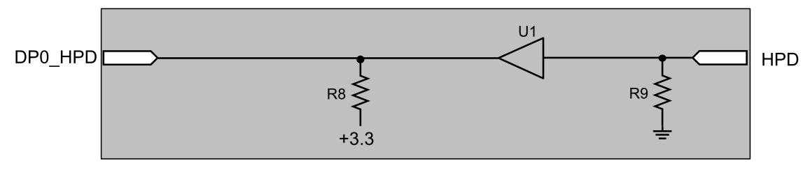
3. about HDMI output, we just reserved chock or need series cap or need add level shift?

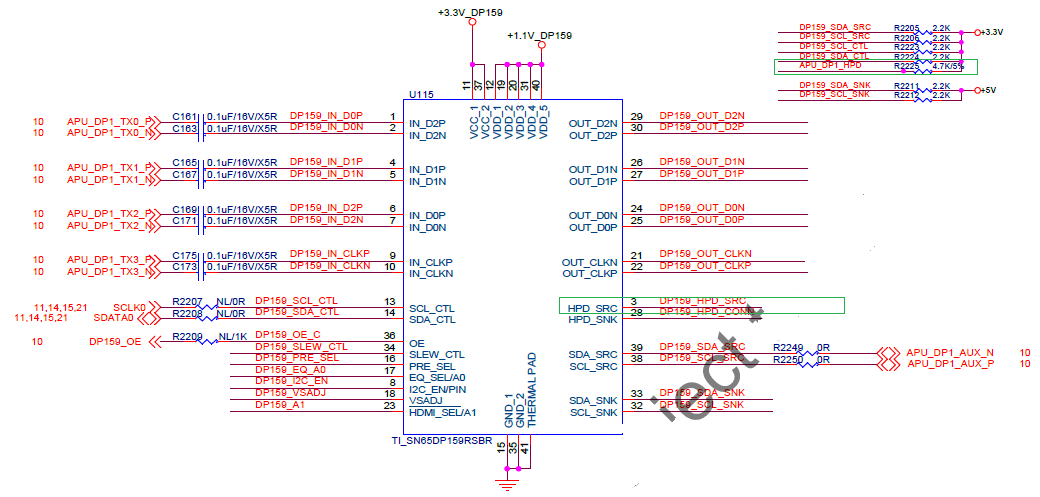
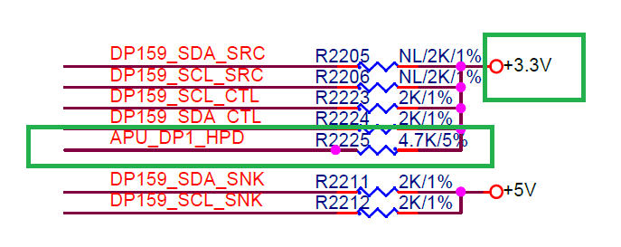
4. I2C Bus address and strap pin we need clarify( EQ_SEL pin was address pin, so need to setting FIXEQ at 7.5db or 14db) how to setting? currently I2C default we setting disable.

below as schematic

2.

3

If any suggestion, Please advise me.

Thanks,

Best regards,

Lawrence.

  • Lawrence

    1. You may need to tune the 0.1uF on the OE pin to meet the power up ramping timing requirement.

    2. For applications where the GPU or Sink does not support clock stretching the DDC lines from the GPU/DP TX should bypass the SCL_SRC and SDA_SRC but still connect to the SCL_SNK and SDA_SNK pins on the DP159. The SCL_SRC and SDA_SRC pins must be pulled to ground. Note that if the GPU/DP TX cannot support the 5V DDC lines from the connector, a level shifter is needed to step down the 5V signals to the voltage level the GPU/DP TX can support.

    3. You may need a level shifter on HPD_SRC depending on the processor HPD voltage level.

    4. Does the processor have separate DDC and AUX or muxed them together?

    5. Please leave EQ_SEL floating for adaptive EQ.

    Thanks

    David

  • Hi David,

    Thanks for your Reply. I checked your comments and bring up some more questions as below:

    1.a. For OE pin, I designed same as EVM which I place a 0.1uF cap on this pin. However, do we Need a serial resistors on TMDS path from SN65DP159 to HDMI sink connector? Please refer to Figure1.

    1.b. Followed above question, do we need to add a passive or active level shift on TMDS path? Please refer to Figure1.

    2. I don't really understand about the sencod question you replyed. If we use DP as SN65DP159 Input, then there is no DDC bus in DP interface, but AUX interface.In this case, should we still connects AUX directly to HDMI connector DDC bus Pins?

    3. Please refer to Figure2/ Figure3-1/ Figure3-2. If we design SN65DP159 on mother board, should we still need to use Level shift for HPD? Because it seems similar as AMD suggestion.

    4. AMD designed AUX and DDC bus in the same ball, it could be program either AUX or DDC.

    5. Is SN65DP159 the re-timer solution from DP to HDMI? Could we use AUX in SN65DP159 and Output to HDMI connector as DDC Bus?

    6. Could SN65DP159 design as HDMI to HDMI re-timer solution?

    Figure1: AC coupling caps for TMDS and Passive Level shift.

    Figure2: AMD schematic diagram demostration.

    Figure3-1: AMD eDP++ Connection

    Figure3-2 AMD HPD Level shift

  • Johnny

    1a. When implementing the external capacitor on the OE pin, the size of the external capacitor depends on the power-up ramp of the VCC supply. You may need to tune the capacitance of this external capacitor since the power-up ramp time of your design will be different from the EVM design.

    1b. I don't fully understand this question. My understanding is that you are designing a DP++ to HDMI solution, the level shifting between DP++ and HDMI is already handled by the DP159. On the output of DP159 to HDMI connector, it will be DC coupled, but you want to place common mode chock on the clock and data lanes.

    3.  HPD on the connector side (HPD_SNK) can be 5V.

    3a. If AMD HPD is connected directly to the HPD of the connector, then from AMD recommendation, it looks like the AMD HPD is a 3.3V signal, so you need a level shifter to shift HPD from 5V down to 3.3V. 

    3b. If HPD goes through the DP159 so the connection is AMD --- HPD_SRC --- DP159 --- HPD_SNK --- HDMI connector, then you don't need the level shifter since HPD_SRC is already a 3.3V signal.

    5a. The DP159 is not a DP to HDMI retimer solution, it is a DP++ to HDMI retimer solution. 

    5b. DP159 supports I2C over AUX, so the connection will be AMD DP++ AUX --- AC coupled --- DP159 AUX --- DP159 DDC_SNK --- DC Coupled --- HDMI connector. On the connection between the DP159 DDC_SNK and the HDMI connector, please make sure you have pullup resistor on DDC_SNK signals.

    6. TMDS181 will be the solution for HDMI to HDMI retimer.

    Thanks

    David

  • Hi David,

    Thanks for your Reply.

    1. We will implment "AMD --- HPD_SRC --- DP159 --- HPD_SNK --- HDMI connector" in our schematic.

    2. Since DP159 is DP++ to HDMI solution, DP159 supports both Input DP and HDMI on data pairs, right?

    in this case

    2a. if we set DP++ as TMDS output (HDMI output) to DP159, then could we use AMD DDC Bus →SDA_SRC/ SCL_SRC → DP159 → SDA_SNK/ SCL_SNK directly? (AMD chip combine DP AUX and HDMI/DVI DDC bus together).

    2b. If we set DP as Output (DP Output ) to DP159, then we must use SN65DP159RGZ, right? because only SN65DP159RGZ supports AUX to I2C (DDC) function.

    3. In the spec TMDS181, it shows it supports to HDMI2.0. But there is a text on first page: Redriver mode supports HDMI1.4b with data rates up to 3.4 Gbps.

        What does this text mean? Could this chipset actually supports to HDMI2.0 (4K2K@60p) when our Input from AMD chipset is HDMI2.0?

    Thanks

  • Johnny

    1. For I2C-over-AUX support, you have to use DP159RGZ. 

    *** Correct. Since DP159RGZ supports I2C-over-AUX, you can have the DP159 AUX connected to the source AUX/DDC.

    2. Since DP159 is DP++ to HDMI solution, DP159 supports both Input DP and HDMI on data pairs, right?

    *** DP159 supports DP and AC-coupled TMDS.

    3. TMDS181 will switch to re-timer mode when in HDMI 2.0.

    Thanks

    David

  • Hi, David

    We saw the SN65DP159 EVM about HPD_SRC pin pull up 1k to board 5V and we pull up 4.7k  to 3.3V(VCC), have any concern?

    If any, Please advise me.

    Thanks,

    Best regards,

    Lawrence.

  • Lawrence:

       HPD_src should be 5v .


    Regards,

    Brian

  • Hi, Brian


    If we use external connect HDMI, so R2225 should be Floating?

    current we design: CPU (HDMI2.0 TMDS)→ SN65DP159→ HDMI output (connector)

    If any suggestion, Please advise me.


    Thanks,

    Best regards,

    Lawrence.

  • so CPU output is  DC coupled TMDS signal? DP159 input should be  DP++ signal or AC coupled TMDS signal

  • can you confirm?

  • Hi, Brian

     as we check AMD PDG, DDI Bus was can support TMDS, and PDG suggestion P/N is SN65DP159.

    So,  HPD_src should be Pull high to 5v or NC?

    Because we use  External  HDMI connector,    

    If any, Please advise me.

    Thanks,

    Best regards,

    Lawrence.

  • Hi, Brian

     as we check AMD PDG, DDI Bus was can support TMDS, and PDG suggestion P/N is SN65DP159.

    So,  HPD_src should be Pull high to 5v or NC?

    Because we use  External  HDMI connector,    

    If any, Please advise me.

    Thanks,

    Best regards,

    Lawrence.

  • Lawrence

    1. You can have HPD from the connector connected to the HPD_SNK of the DP159, and then have the HPD_SRC of the DP159 connected to the AMD HPD signal. Or

    2. You can have HPD from the connector connected to the AMD HPD signal, and HPD_SNK of the DP159 connected to this direct connection between the AMD and the connector.

    For the #1 implementation, HPD_SRC of the DP159 is a 3.3V signal. Please check the AMD HPD input voltage requirement. If AMD HPD is a 5V signal, then you need to step up from 3.3V to 5V. If AMD HPD is a 3.3V signal, then it is a direct connection between the HPD_SRC of the DP159 to the AMD HPD.

    Thanks

    David