Other Parts Discussed in Thread: DS90UB935-Q1
Dear Sir,
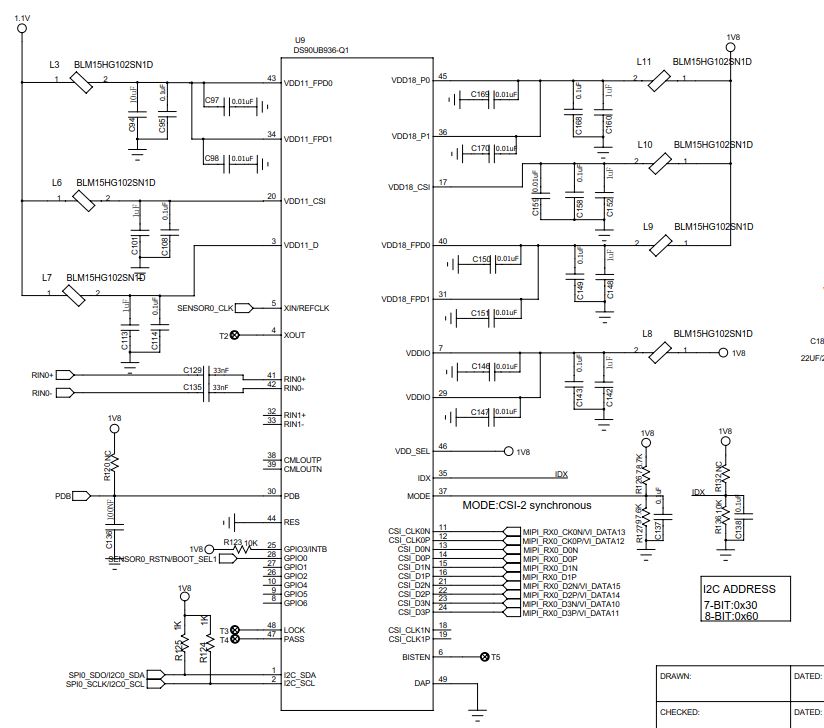
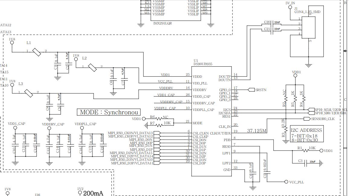
936 mode pin is in mode#4, 935 mode pin is in mode#0
In the case that the above synchronization mode cannot be locked, customer changes the 0X58 register of 936 to 0X5A (936 works in non-synchronous mode). At this time 935 does not change, 935 and 936 can be LOCK, and LOCK is stable.
But we can't read/write front end SENSOR, we use in the STP mode, how to setting the 935/936 ?
The attached file is code and sensor.IMX327LQR-C_TechnicalDatasheet_E_Rev0.2.pdf
#include <stdio.h>
#include <sys/types.h>
#include <sys/stat.h>
#include <sys/ioctl.h>
#include <fcntl.h>
#include <unistd.h>

#define I2C_RETRIES     0x0701  /* number of times a device address should
                   be polled when not acknowledging */
#define I2C_TIMEOUT     0x0702  /* set timeout in units of 10 ms */

/* NOTE: Slave address is 7 or 10 bits, but 10-bit addresses
 * are NOT supported! (due to code brokenness)
 */
#define I2C_SLAVE       0x0703  /* Use this slave address */
#define I2C_SLAVE_FORCE 0x0706  /* Use this slave address, even if it is already in use by a driver! */
#define I2C_TENBIT      0x0704  /* 0 for 7 bit addrs, != 0 for 10 bit */

#define I2C_FUNCS       0x0705  /* Get the adapter functionality mask */

#define I2C_RDWR        0x0707  /* Combined R/W transfer (one STOP only) */

#define I2C_PEC         0x0708  /* != 0 to use PEC with SMBus */
#define I2C_SMBUS       0x0720  /* SMBus transfer */
#define I2C_16BIT_REG   0x0709  /* 16BIT REG WIDTH */
#define I2C_16BIT_DATA  0x070a  /* 16BIT DATA WIDTH */


const unsigned int  imx327_addr_byte    =    2;
const unsigned int  imx327_data_byte    =    1;
const unsigned char imx327_i2c_addr     =    0x34;
const unsigned char imx327_i2c_vir_addr     =    0x36;


const unsigned char Ti935_i2c_addr     =    0x30;        /* I2C Address of Ti935_i2c_addr */
const unsigned char Ti935_i2c_vir_addr     =    0x32;        /* I2C Address of Ti935_i2c_addr */

const unsigned char Ti936_i2c_addr     =    0x60;        /* I2C Address of Ti936_i2c_addr */

static int g_fd = 0;


int imx327_write_register(int addr, int data)
{
    if (0 > g_fd)
    {
        return 0;
    }

    int idx = 0;
    int ret;
    char buf[8];

    if (imx327_addr_byte == 2)
    {
        buf[idx] = (addr >> 8) & 0xff;
        idx++;
        buf[idx] = addr & 0xff;
        idx++;
    }
    else
    {
        //buf[idx] = addr & 0xff;
        //idx++;
    }

    if (imx327_data_byte == 2)
    {
        //buf[idx] = (data >> 8) & 0xff;
        //idx++;
        //buf[idx] = data & 0xff;
        //idx++;
    }
    else
    {
        buf[idx] = data & 0xff;
        idx++;
    }

    ret = write(g_fd, buf, imx327_addr_byte + imx327_data_byte);
    if (ret < 0)
    {
        printf("I2C_WRITE error!\n");
        return -1;
    }

    return 0;
}


int imx327_read_register(int addr, int data)
{
    // TODO:
	int ret;
	int idx = 0;
	char buf[8];
	char recbuf = 0;

	//buf[idx] = addr & 0xff;
	//idx++;

    if (imx327_addr_byte == 2)
    {
        buf[idx] = (addr >> 8) & 0xff;
        idx++;
        buf[idx] = addr & 0xff;
        idx++;
    }

	//send reg address
	ret = write(g_fd, buf, 2);
	if(ret<0)
	{
		printf("I2C_WRITE error!\n");
		return -1;
	}

	//get data
	ret = read(g_fd, &recbuf, 1);
	if(ret<0)
	{
		printf("I2C_READ error!\n");
		return -1;
	}

	printf("[imx327 Read] addr:%#x data:%#x\n",addr,recbuf);

    return 0;

}

int read_register_8bitAddr(int addr, int readlen)
{
    // TODO:
	int ret;
	int idx = 0;
	char buf[8];
	char recbuf = 0;

	buf[idx] = addr & 0xff;
	idx++;

	//send reg address
	ret = write(g_fd, buf, 1);
	if(ret<0)
	{
		printf("I2C_WRITE error!\n");
		return -1;
	}

	//get data
	ret = read(g_fd, &recbuf, 1);
	if(ret<0)
	{
		printf("I2C_READ error!\n");
		return -1;
	}

	printf("[Read] addr:%#x data:%#x\n",addr,recbuf);

    return 0;
}

int write_register_8bitAddr(int addr, int data)
{
	if (0 > g_fd)
	{
		return 0;
	}

	int idx = 0;
	int ret;
	char buf[8];

	buf[idx] = addr & 0xff;
	idx++;

	buf[idx] = data & 0xff;
	idx++;

	ret = write(g_fd, buf, 1 + 1);
	if (ret < 0)
	{
		printf("I2C_WRITE error!\n");
		return -1;
	}

	printf("[Write] addr:%#x data:%#x\n",addr,data);


	return 0;
}

int i2c_init(unsigned char i2c_addr)
{
    char acDevFile[16] = {0};
    unsigned char u8DevNum;

    //if (g_fd >= 0)
    //{
    //    return 0;
    //}

    int ret;

    u8DevNum = 0;//g_aunImx327BusInfo[ViPipe].s8I2cDev;
    snprintf(acDevFile, sizeof(acDevFile),  "/dev/i2c-%u", u8DevNum);

    g_fd = open(acDevFile, O_RDWR, S_IRUSR | S_IWUSR);

    if (g_fd < 0)
    {
        printf("Open /dev/hi_i2c_drv-%u error!\n", u8DevNum);
        return -1;
    }

    ret = ioctl(g_fd, I2C_SLAVE_FORCE, (i2c_addr >> 1));
	//ret = ioctl(g_fd, I2C_SLAVE, (i2c_addr >> 1));
    if (ret < 0)
    {
        printf("I2C_SLAVE_FORCE error!\n");
        close(g_fd);
        g_fd= -1;
        return ret;
    }
	printf("[Init] acDevFile:%s slave:%#x\n",acDevFile,i2c_addr);

    return 0;
}

int i2c_exit()
{
    if (g_fd >= 0)
    {
        close(g_fd);
        g_fd = -1;
        return 0;
    }
    return -1;
}

#if 0
int Ti_ub936()
{
	printf("----------936\n");

	i2c_init(Ti936_i2c_addr);

	read_register_8bitAddr(0x00,1);//936 i2c��ַ
	read_register_8bitAddr(0x6d,1);
	read_register_8bitAddr(0x58,1);


	//FPD3_PORT_SEL 0x4c
	read_register_8bitAddr(0x4c,1);
	write_register_8bitAddr(0x4c,0x01);//RxPort 0 enable
	//write_register_8bitAddr(0x4c,0x0f);//sample
	read_register_8bitAddr(0x4c,1);

	//Port_Config
	write_register_8bitAddr(0x6d,0x58);

	//BCC_CONFIG 0x58
	//write_register_8bitAddr(0x58,0x58);
	write_register_8bitAddr(0x58,0x7a); //10Mbps non_sync
	//write_register_8bitAddr(0x58,0x7d); //25Mbps
	//write_register_8bitAddr(0x58,0x7e); //50Mbps sync
	//write_register_8bitAddr(0x58,0x7F); //100Mbps

	//write_register_8bitAddr(0x58,0xfa); //10Mbps non_sync
	//write_register_8bitAddr(0x58,0xfd); //25Mbps
	//write_register_8bitAddr(0x58,0xfe); //50Mbps sync
	//write_register_8bitAddr(0x58,0xfF); //100Mbps

	read_register_8bitAddr(0x58,1);

	//935 iic id
	write_register_8bitAddr(0x5c,0x31);
	read_register_8bitAddr(0x5c,1);

	//sensor iic id
	write_register_8bitAddr(0x5d, 0x34); //Slave_ID[0],Զ��iic�ĵ�ַ
	read_register_8bitAddr(0x5d,1);

	write_register_8bitAddr(0x65, 0x35); //Slave_Alias[0]��ӳ������iic��ַ
	read_register_8bitAddr(0x65,1);

	i2c_exit();

	return 0;
}


int Ti_ub935()
{
#if 1

		printf("----------935\n");
		i2c_init(Ti935_i2c_vir_addr);
		read_register_8bitAddr(0x00,1);//935 i2c��ַ
		read_register_8bitAddr(0x02,1);//935 MODE_SEL
		read_register_8bitAddr(0x03,1);//935 MODE_SEL
		read_register_8bitAddr(0x0d,1);//935  LOCAL_GPIO_DATA
		read_register_8bitAddr(0x53,1);//935  GPIO_PIN_STS
		read_register_8bitAddr(0x0e,1);//935
		//write_register_8bitAddr(0x32,0x69);//935 BCC_CONFIG pass auto_ack
		//write_register_8bitAddr(0x32,0xe9);//935 BCC_CONFIG pass auto_ack
		//write_register_8bitAddr(0x0d,0x10);//935  �ij�Զ��ӳ��936 ��GPIO0����
		//write_register_8bitAddr(0x0e,0xF0);//935  GPIO_INPUT_CTRL //�ij����ģʽ
		read_register_8bitAddr(0x0e,1);//935
		read_register_8bitAddr(0x0d,1);//935
		read_register_8bitAddr(0x53,1);//935  GPIO_PIN_STS


		//write_register_8bitAddr(0x05,0x1b);
		//write_register_8bitAddr(0x06,0x29); //HS_CLK_DIV = 4 M = 9
		//write_register_8bitAddr(0x07,0xf2); //N = 0xF2

		//write_register_8bitAddr(0x03,0x5a); //��ͬ���ⲿʱ��ģʽ

		i2c_exit();

#endif

	return 0;
}
#endif

int Ti_ub936()
{
	printf("----------936\n");

	i2c_init(Ti936_i2c_addr);
	write_register_8bitAddr(0x01, 0x03);		//reset
	write_register_8bitAddr(0x33, 0x23);		//Enable CSI, Line2-Line, Continue Clock

	write_register_8bitAddr(0x4c, 0x01);		// Port Select 0
	write_register_8bitAddr(0x20,0x08);			// Forward Port Select 0

	//write_register_8bitAddr(0x58,0x7a); 		//10mbps no_sync  (can lock)
	write_register_8bitAddr(0x58,0x7e);			//50mbps sync     (can't lock!)

	write_register_8bitAddr(0x7c,0x81);			//PORT_CONFIG2

	write_register_8bitAddr(0x5b,Ti935_i2c_addr);		//serid
	write_register_8bitAddr(0x5c,Ti935_i2c_vir_addr);	//seraliasid

	//sensor iic id
	write_register_8bitAddr(0x5d, imx327_i2c_addr); //Slave_ID[0]
	read_register_8bitAddr(0x5d,1);

	write_register_8bitAddr(0x65, imx327_i2c_vir_addr); //Slave_Alias[0]
	read_register_8bitAddr(0x65,1);


	i2c_exit();

	return 0;
}


int Ti_ub935()
{
#if 1

		printf("----------935\n");
		i2c_init(Ti935_i2c_vir_addr);
		read_register_8bitAddr(0x00,1);//935 i2c��ַ
		read_register_8bitAddr(0x02,1);//935 MODE_SEL
		read_register_8bitAddr(0x03,1);//935 MODE_SEL
		read_register_8bitAddr(0x0d,1);//935  LOCAL_GPIO_DATA
		read_register_8bitAddr(0x53,1);//935  GPIO_PIN_STS

		i2c_exit();

#endif

	return 0;
}


int IMX327_init()
{

	printf("----------imx327\n");
	i2c_init(imx327_i2c_vir_addr);
	//imx327_write_register (0x3000, 0x01); /* STANDBY */
	imx327_read_register(0x3000, 0x01); /* STANDBY */

	i2c_exit();


	return 0;
}


int main(int argc, char * * argv)
{

	Ti_ub936();
	sleep(1);
	Ti_ub935();
	sleep(1);
	IMX327_init();


#if 0
	//test
	i2c_init(Ti936_i2c_addr);
	write_register_8bitAddr(0x33,0x01);

	write_register_8bitAddr(0xB0,0x00);
	write_register_8bitAddr(0xB1,0x01);
	write_register_8bitAddr(0xB2,0x01);

	write_register_8bitAddr(0xB1,0x02);
	write_register_8bitAddr(0xB2,0x33);

	write_register_8bitAddr(0xB1,0x03);
	write_register_8bitAddr(0xB2,0x24);

	write_register_8bitAddr(0xB1,0x04);
	write_register_8bitAddr(0xB2,0x0F);

	write_register_8bitAddr(0xB1,0x05);
	write_register_8bitAddr(0xB2,0x00);

	write_register_8bitAddr(0xB1,0x06);
	write_register_8bitAddr(0xB2,0x01);

	write_register_8bitAddr(0xB1,0x07);
	write_register_8bitAddr(0xB2,0xE0);

	write_register_8bitAddr(0xB1,0x08);
	write_register_8bitAddr(0xB2,0x02);

	write_register_8bitAddr(0xB1,0x09);
	write_register_8bitAddr(0xB2,0xD0);

	write_register_8bitAddr(0xB1,0x0a);
	write_register_8bitAddr(0xB2,0x04);

	write_register_8bitAddr(0xB1,0x0b);
	write_register_8bitAddr(0xB2,0x1a);

	write_register_8bitAddr(0xB1,0x0c);
	write_register_8bitAddr(0xB2,0x0c);

	write_register_8bitAddr(0xB1,0x0d);
	write_register_8bitAddr(0xB2,0x67);

	write_register_8bitAddr(0xB1,0x0e);
	write_register_8bitAddr(0xB2,0x21);

	write_register_8bitAddr(0xB1,0x0f);
	write_register_8bitAddr(0xB2,0x0a);

#endif

	return 0;
}