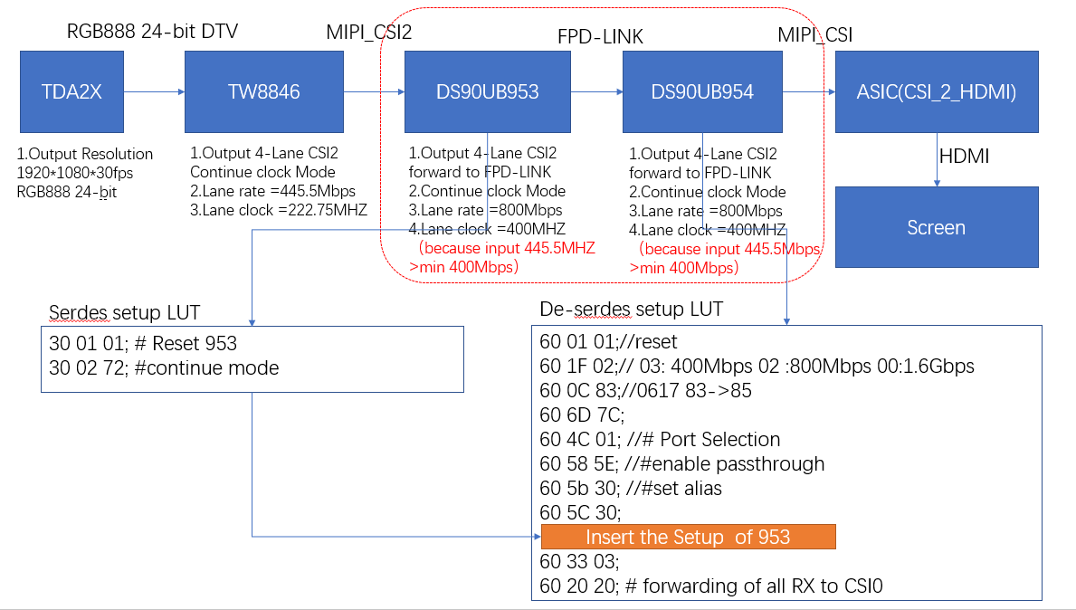
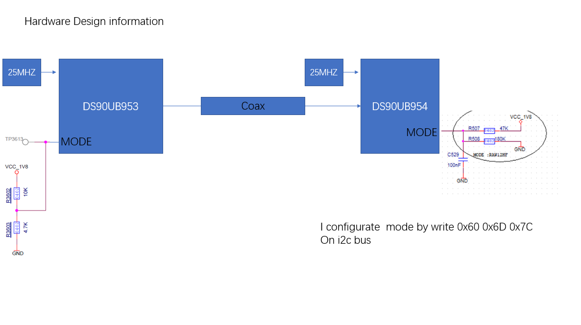
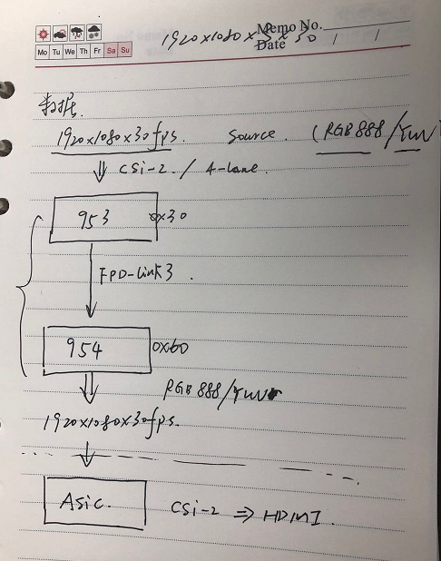
Now i use DS90UB953 fit with DS90UB954,my image source is RGB888/YUV422 4-lane CSI ,image size 1920*1080*30fps,i have confirmed that my hardware designing is OK just use an config-lut like fellow
my application blockgram is that:
/******************************************************************************************/
init 954:
/*******************************************************************************************/
;@@ TI954
60 0C 0f;//I2C mapping pass port0 enable port0
60 1F 02;//CSI_PLL_CTL 800Mbps for 720p YUV422
60 0C 0f;//I2C mapping pass port0 enable port0
60 1F 02;//CSI_PLL_CTL 800Mbps for 720p YUV422
//GPIO config 0x10 -0x16,Not care
// Frame sync config Not care
60 4c 01;//page to port RX0
60 58 58;//enable passthrough
60 5b 30;//serializer-DS90UB953 slave ID=0x30
60 5c 30;//serializer alias ID
60 5d 6c;//imager slave id
60 65 22;//image
60 6d 7c;//input mode 953/935 适配
60 7c 01;//set frame valid polarity to active high
60 58 58;//enable passthrough
60 5b 30;//serializer-DS90UB953 slave ID=0x30
60 5c 30;//serializer alias ID
60 5d 6c;//imager slave id
60 65 22;//image
60 6d 7c;//input mode 953/935 适配
60 7c 01;//set frame valid polarity to active high
60 4C 12;//page to port RX1
60 58 58;//enable passthrough
60 5b b0;//serializer slave ID = 0x30
60 5c b4;//serializer
60 5d 6C;//imager slave ID = 0x30
60 65 24;//imager slave alias, port0
60 6d 7e;//set input mode
60 7c 01;//set frame valid polarity to active high
60 58 58;//enable passthrough
60 5b b0;//serializer slave ID = 0x30
60 5c b4;//serializer
60 5d 6C;//imager slave ID = 0x30
60 65 24;//imager slave alias, port0
60 6d 7e;//set input mode
60 7c 01;//set frame valid polarity to active high
;@@ MIPI init
60 4C 0F;//
60 0F 00;//disable GPIO input
60 4C 01;//port 0 format
60 70 2b;
60 71 2c;
60 72 00;
60 4C 0F;//
60 0F 00;//disable GPIO input
60 4C 01;//port 0 format
60 70 2b;
60 71 2c;
60 72 00;
60 4C 12;//port 1 format
60 70 2b;
60 71 2c;
60 72 00;
60 70 2b;
60 71 2c;
60 72 00;
60 33 23;//'enable CSI port0
60 20 00;//'[3:0]: 0: CSI-2 port 0; 1: CSI-2 port 1;
60 21 03;//'For Fred
60 20 00;//'[3:0]: 0: CSI-2 port 0; 1: CSI-2 port 1;
60 21 03;//'For Fred
/*************************************************************************************/
init DS90UB953 to test pattern generator mode:
/*************************************************************************************/
30 B0 00;//# Indirect Pattern Gen Registers
30 B1 01;//# PGEN_CTL
30 B2 01;//
30 B1 02;//# PGEN_CFG
30 B2 33;//
30 B1 03;//# PGEN_CSI_DI
30 B2 24;//# RGB888
30 B1 04;//# PGEN_LINE_SIZE1
30 B2 16;//
30 B1 05;//# PGEN_LINE_SIZE0
30 B2 80;//
30 B1 06;//# PGEN_BAR_SIZE1
30 B2 02;//
30 B1 07;//# PGEN_BAR_SIZE0
30 B2 D0;//
30 B1 08;//# PGEN_ACT_LPF1
30 B2 04;//
30 B1 09;//# PGEN_ACT_LPF0
30 B2 38;//
30 B1 0A;//# PGEN_TOT_LPF1
30 B2 04;//
30 B1 0B;//# PGEN_TOT_LPF0
30 B2 65;//
30 B1 0C;//# PGEN_LINE_PD1
30 B2 0B;//
30 B1 0D;//# PGEN_LINE_PD0
30 B2 93;//
30 B1 0E;//# PGEN_VBP
30 B2 21;//
30 B1 0F;//# PGEN_VFP
30 B2 0A;//
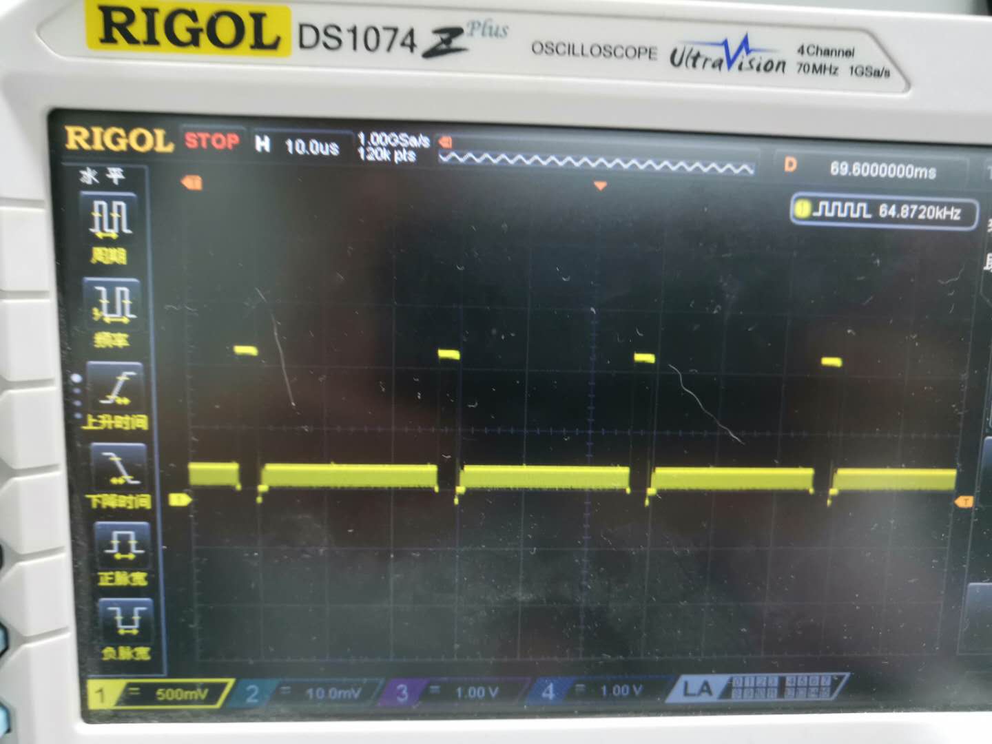
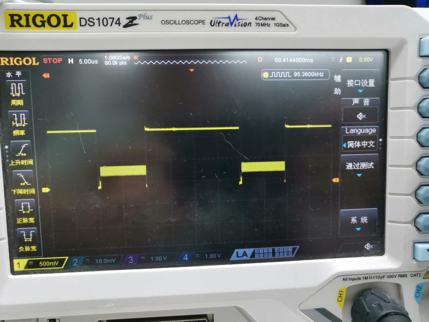
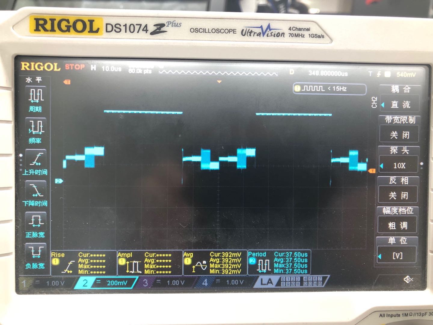
then i check the signal output from DS90UB954 CSI-PORT
so ①how to modify the config to make it not to use virtul channel
② if use an real image source input but not the test pattern,how to change the config lut?
3:how does 953&954 know whether the input is RGB888 or YUV and how to make it suit to 的signal?