This thread has been locked.

If you have a related question, please click the "Ask a related question" button in the top right corner. The newly created question will be automatically linked to this question.

TUSB320: TUSB320RWBR OTG auto detect

Part Number: TUSB320
Other Parts Discussed in Thread: TUSB321, ,

Hi Sirs,

Sorry to bother you.

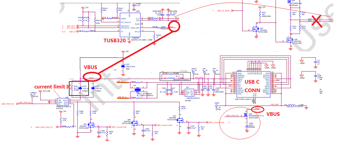
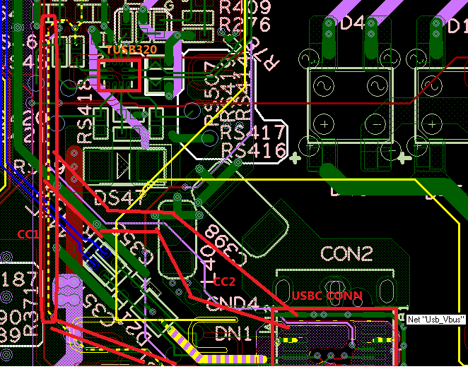
Our schematic as below.

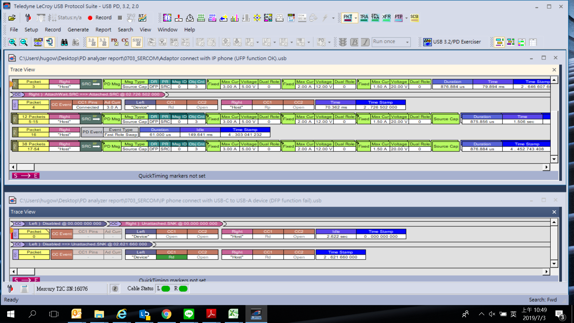
Our USB C is connected to the computer through the cable. The Type C connector is inserted in a certain direction. The level of cc1/cc2 is about 0.45V, and the other side is inserted, cc1/cc2 level. It is 0, but the USB_ID of both states is high.

Looks it's not be automatic detecttion .
Could you help to check i?, thanks!!.

  • if you need cable orientation detection, you may need TUSB321, DIR pin will tell you the plug orientation 

  • Hi Sirs,

    Thanks for your reply.

    There have three question as below, could you help to check it?

    1. If we don't need direction identification, is OK for  use TUSB320?

    2. We use the USB 3.0 A/C adapter to connect the USB flash drive. The board  supply power is from POE to supply power.

    We think the board should be in the host state.

    But measured, the two CCs are in the state of continuous switching between high and low levels, the ID has no change - always high level

    3. Using USB C connect to the computer directly via USB 2.0 cable 

      a) The board is powered by POE. The measured two CCs are at 0.4V/0V low level, and the ID has no change - always high level.
      b) The board is directly connected to the PC and powered by the computer. The measured two CCs are at 0.4V/0V low level, and the ID has no change - always high level.

  • Hi Sirs,

    Sorry for pushed, any update on this case?

    Thanks!!

  • Hi,

    1. TUSB320 can be used if DIR pin is not needed.

    2&3.It seems that your device may be in DRP mode, can you I2C configuration of the TUSB320? Are you seeing ID pin always high on multiple devices/platforms?

    It is important to remember that type c cables only carry one CC line across the cable, so one CC line at 0 V this should be expected in the normal case. This device is bus powered in this application? Is the accessory mode enabled? Could you capture the wave form for a longer period of time?

  • Dear sir:

    This is Sally Feng from Sercomm, thanks for your reply! And we're confusing about the usage of TUSB320, we are expecting to use it as DRP mode on our board, but now it seems that it can't give the detection, we powered the board by POE, left the USB C port as a OTG port,  the CC keeps switching and the ID keeps high no matter dis-connected or inserted any device, any mistake on schematic configuration?

    we do nothing on the I2C now, any configuarion on it needed?

    and we've checked the CC and ID keeps the states for a very long time, evan more than 10 minutes, no changes occured.

    thanks

    Sally

  • Dear sir:

    Any comment?  thanks

    Sally Feng

  • Hi,

    In your application TUSB320 maybe being back powered through the non-fail safe pins causing the device to be stuck in a incorrect state.

    TUSB320 non-failsafe pins (VBUS_DET, ADDR, PORT, ID, OUT[3:1] pins) could back-drive the TUSB320 device if not handled properly. When necessary to pull these pins up, it is recommended to pullup PORT, ADDR, INT_N/OUT3, and ID to the device VDD supply. The VBUS_DET must be pulled up to VBUS through a 900-kΩ resistor. When using the 3.3 V supply for I 2C, the end user must ensure that the VDD is 3 V and above. Otherwise the I 2C may back power the device.

    Could you look into the following questions:

    • When does TUSB320 EN_N pin go low? Is this pin held high at least for 50 ms after VDD has reached its valid voltage level. Does VDD must ramp within 25 ms or less (This is probably the case but I would like to confirm)?
    • Is it possible to power the TUSB320 externally (non-Vbus power) and see if the same issues are experienced? 

  • Dear sir:

    We've changed the VDD to system 3v3, the voltage is 3.35V>3.0V, the symptom are same,

    about the EN_N, it keeps low without holding high after powering up, and the VDD comes up to 3.3V quickly within 25mins

    And, if we remove the VBUS_DET, the detection seems OK(at least for host mode), what's the mode IC in without VBUS_det, why the VBUS_DET cause the detection fail?

    thanks

    Sally

  • Hi,

    It seems that VBUS_DET may have been back driving TUSB320. VBUS_Det helps to determine if a USB device is attached in UFP mode. If TUSB320 is back powered it can get into a unknow state and drive some of the outputs. Does the ID pin still stay high when VBUS_DET is connected? Could you describe the application?

  • Dear sir:

    Yes, if the VBUS_DET is connected, the ID stays high, no matter devices inserted or not.

    and if VBUS_DET not connected in DRP mode, or  TUSB320 configured as a DFP mode(VBUS_DET connected, PORT to VDD), the host mode works, ID changes to low when devices insered.

    Please refer to the attached schematic about the USB C port application, we used the USB C as a DRP mode as well as DC power input port.

    thanks

    Sally

  • Dear sir:

    Sorry, any idea about our application?

    thanks

    Sally Feng

  • Hi Sirs,

    Sorry for pushed, have any update on this case?

    Thanks!!

  • Hi,

    sorry about the delay. After some investigation ID should only be affected by CC pin voltage level and if the CC pin voltage level is latched at Rd levels then ID will say low in connect or disconnect states. Is there something on the CC lines that could be causing the toggling? I did not see anything in the schematic.

  • Dear sir:

    Yes, as shown in the schematic, there is nothing else on CC pin when testing, but we reserved the manual CC switch circuit, that cause a long path for CC1 and CC2, does the layout effect the CC detection?

    thanks

  • Hi,

    On the CC line toggling, CC 1 and CC 2 will toggle when TUSB320 is configured to support accessory devices in UFP mode or in DRP (waiting for connection) ID should be asserted low when CC pin detected device attachment when port is a source (DFP), or dual-role (DRP) acting as source (DFP). In UFP mode TUSB320 will hold ID in tri-state, which is why ID may be held high always in this case. Could you verify that TUSB320 is not in UFP mode or DRP presenting as UFP? Also to confirm, you are using TUSB320 and not TUSB320LAI/HAI, correct?

  • Dear sir:

    We use TUSB320RWBR.

    And we configured TUSB320 as a DRP that follow the datasheet's reference, just as the schematic shows, the CC keeps switching and ID keeps high at the same time, when devices inserted, that's the point  I doubt it doesn't enter the correct mode(DFP) by detection automatically. BTW, why the ID in tri-stae when entering DFP mode?  we always saw it in high.

    thanks

    Sally

  • Hi,

    TUSB320 should have the CC switching and ID high at the same time when no device is connected. We can confirm what mode the device is going into through the I2C registers. Are you able to read the I2C registers? What are the values of ATTACHED_STATE and MODE_SELECT when a device is unconnected versus connected? The ID pin will be tri-sate when in DRP mode is acting as UFP. 

  • Sally:

       any update?

  • Hi Sirs,

    Thanks for your reply.

    We have to log USB protocol as below.

    Looks our device always be fixed on UFP mode.

    But we are setting TUSB320 to DRP mode.

    So could you help check what wrong for our design?

    By the way, our application is IP phone.

    Schematic:

    Schematic-已編輯.pdf

    1. Adapter connect to IP Phone ( UFP function OK)

    2. IP phone connect to (USB-C to USB-A device) (DFP function fail). 

  • Hi Sirs,

    Sorry for pushed, any update on this case?

  • Hi Sirs,

    Sorry for pushed, any update on this case?

  • do you have vbus switch ? for  DFP, Vbus should not be connected before a UFP is connected.

  • Hi Sirs,

    Thanks for your reply

    It is verified that after changing the VBUS power supply timing, DFP Mode detection can be implemented.
    However, there is a problem that the level of the ID pin cannot be adjusted.

    If the pull-up resistor RS419 is 200K, the storage is connected or not, and the ID pin level is 2.2V.

    The RS419 is adjusted to 300 ohm or less. When the storage is not connected, the ID pin level is 3.3V. When the storage is connected, the ID pin output level is still 2.2What is the reason?

  • Hi Sirs,

    Sorry for pushed, have any update on here?

  • what the voltage on CC pin in DFP mode?

  • Hi Brian,

    Thanks for your reply.

    CC1 had 570mV, CC2 still keep low voltage level.

  • Hi Sirs,

    Sorry for pushed, have any update on here?

  • probably still no in DFP mode, after plug in, you will see one cc pin high/one cc pin low. once MCU see ID goes low than turn on the Vbus. so Vbus should be on after ID pin goes low.

  • Hi Sirs,

    Thanks for your reply

    At present, our board can already read the device access, but the high-speed device link only has full-speed.

    Did you know what is the reason?

    By the way, is possible to hold a con-call to you at tomorrow morning ? Our location's time is (GMT +8). We could refer your time

    Thanks!!

  • Hi,

    Would you be able to private message me about the con-call? 

  • Is there any more support needed for this issue? If so please reply with any relevant details so that I can further assist you. For now I will be marking this thread as "TI Thinks Resolved". If you have resolved your issue, please post the solution to the original problem/post for others with similar issues.

  • Hi Sirs,

    Thanks for your reply, after add power switch to control power sequence looks the function could be work on DFP.

    I'll to close this topic.

    Thanks!!