This thread has been locked.

If you have a related question, please click the "Ask a related question" button in the top right corner. The newly created question will be automatically linked to this question.

DS110DF410: How to configure DS110DF410 in Manual EQ and CDR bypass mode.

Part Number: DS110DF410
Other Parts Discussed in Thread: DS125DF111EVM, , DS110DF111

Hi Team,

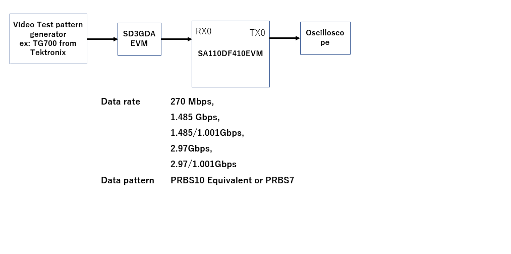
Please advice me on configuring DS110DF410 in Manual EQ and CDR bypass mode.
Referring the datasheet, I created a script as shown bellow.
The DS110DF410 moves into an intended mode.
However, I faced a problem.

The DS110DF410 output was intermittently muted for about 5 us.
This occurred several times in about 10 ms.
Please help me resolving this problem

~~~~~~~~~~~~~~~~~~~~~~~~~~~~~~~~~~~~~~~~~~~~~~~~~~~
import smbus
import time
import math
bus = smbus.SMBus(1)
# DS119DF410 I2X buss addres = 0x30

i2c_address = 0x30
EQ1 = 0x00

# Config DS110DF410 CH0

bus.write_byte_data(i2c_address/2, 0xff, 0x04)

# Set EQ in manual mode

value = bus.read_byte_data(i2c_address/2, 0x31) # EQ Mod = No Adaptation
value = (value & 0x9f) | 0x00 # Mask = 0x60
bus.write_byte_data(i2c_address/2, 0x31, value)

bus.write_byte_data(i2c_address/2, 0x3a, EQ1) bus.write_byte_data(i2c_address/2, 0x03, EQ1)

bus.write_byte_data(i2c_address/2, 0x0a, 0x1c) # RESET CDR
time.sleep(0.001)
bus.write_byte_data(i2c_address/2, 0x0a, 0x18) # De-Assert RESET CDR
time.sleep (0.02)

# Set CDR in bypass mode

bus.write_byte_data(i2c_address/2, 0x09, 0x20) bus.write_byte_data(i2c_address/2, 0x1e, 0x09)

~~~~~~~~~~~~~~~~~~~~~~~~~~~~~~~~~~~~~~~~~~~~~~~~~~~~~~~

Mita

  • Hello Team,

    As Mita-san had posted above, our customer wants to use DS110DF410 in REPEATER mode (Bypass CDR) to equalize the data rate such as 3G-SDI (2.97Gbps) and HD-SDI (1.485Gbps).

    If the device is in REPEATER mode, I believe there is no limitation from the CDR VCO frequency range and could support data rate under 11.3Gbps.

    Q1). How can we achieve this ? Could you please advise us the register setting procedure ?
      We are using the above script** to bypass CDR and to fix the CTLE gain.

    Q2). When we ran above script and applied 3G-SDI signal, we observed output signal muting for 5us in every 15ms. Why does this happen ?


    ** Script Summary (Register Setting)

    REG 0xFF = 0x04     //Select Channel A
    REG 0x31 = 0x00     //No Adaptation Mode (Fixed Gain)
    REG 0x03 = 0x00     //EQ Boost = 0x00 (minimum)
    REG 0x3A = 0x00     //EQ Boost = 0x00 (minimum)
    REG 0x0A = 0x1C     //CDR Reset Assert
    REG 0x0A = 0x18     //CDR Reset De-Assert
    REG 0x09 = 0x20     //Enable Override Output MUX
    REG 0x1E = 0x09    //Disable DFE, Select Output MUX as RAW data


    Best Regards,

    Kawai

  • assign to right person

  • Hello Team,

    It would be helpful if we could have your advice by your 6/25, since we are having a meeting tomorrow.

    Thanks in advance.

    Best Regards,

    Kawai

  • The routine below captured in your previous message for setting CDR bypass and manual EQ is correct.

    REG 0xFF = 0x04     //Select Channel A
    REG 0x31 = 0x00     //No Adaptation Mode (Fixed Gain)
    REG 0x03 = 0x00     //EQ Boost = 0x00 (minimum)
    REG 0x3A = 0x00     //EQ Boost = 0x00 (minimum)
    REG 0x0A = 0x1C     //CDR Reset Assert
    REG 0x0A = 0x18     //CDR Reset De-Assert
    REG 0x09 = 0x20     //Enable Override Output MUX
    REG 0x1E = 0x09    //Disable DFE, Select Output MUX as RAW data

    What is the specific data rate and test pattern being used by customer when issue is observed? Do note that the DS110DF410 was not designed for SDI applications.

    Regards,

    Rodrigo Natal

  • Rodrigo-san,

    I have confirmed that DS110DF410 was manual EQ and CDR bypass mode with
    above register modification.

    However, I experienced one problem.
    The DS110DF410 output port was periodically disables for about 5 us.
    The interval of the disable was 1.5 ms but validated depending on

    Please check the DS110DF410 output using EVM.

    Mita

  • I need the question below to be addressed in order to be able to provide any advice.

    • What is the specific data rate and test pattern being used by customer when issue is observed?

    In addition, a system block diagram would be useful here. In particular, Is the customer implementing AC coupling caps on the retimer inputs and outputs?

    Thanks,

    Rodrigo Natal

    HSSC Applications Engineer

  • Rodorigo-san

    I sued color bar and tested at SD, HD and 3G.

    All cases I see this symptom

    Mita

  • Rodrigo-san,

    Can you let me know how to stop CDR state machine.

    I suspect that CDR state machine may case this symptom.

    I tried Reset CDR and see it made  output disabled.

    Mita

  • Hi Rodrigo-san,

    Thanks for your kind support.

    Maybe you could try a simple test applying 3Gbps PRBS signal to DS110DF410 with the register settings above.

    I believe you could observe the same symptom.

    ** Added following information **

    When we tested with DS125DF111EVM, it was able to output the correct signal (No periodical mute) for data rate 2.97Gbps or 3Gbps with CDR byapss (Output MUX = RAW).
    It seems the CDR is related to this periodical output muting symptom on DS110DF410. Our guess is that even if the output MUX is set to RAW data, input signal is also connected to CDR block which is still operating and is trying to acquire lock for every 15ms.

    Is there any possibility that the CDR algorithm would mute output when the data rate is outside the VCO frequency range even when the CDR is bypassed, repeater mode ?

    Best Regards,

    Kawai

  • Kawi-san,

    Please, I respectfully ask again that you address my questions. This is starting to become irritating.

    • What is the specific data rate and test pattern being used by customer when issue is observed?
    • In addition, a system block diagram would be useful here. In particular, Is the customer implementing AC coupling caps on the retimer inputs and outputs?

    We have tested CDR bypass mode extensively on this retimer. Whether or not CDR is locked should have no bearing on the data output when the CDR bypass is enabled while 0x09[5]=1. For standard 8B/10B or 64B/66B encoded data I do not expect any issue

    One test you may try is forcing signal detect asserted by setting channel register 0x14[7]=1 while operating in CDR bypass mode. Right now my hypothesis is that signal detect loss is being triggered by low transition density bits within the customer's data stream.

    Thanks,

    Rodrigo Natal

    HSSC Applications Engineer

  • Hello Rodrigo-san,

    Here is my comments below

    • What is the specific data rate and test pattern being used by customer when issue is observed?
      • As noted above, based on our test, we observed exact the same symptom with customer using PRBS-7 pattern at 3.00Gbps.
      • Customer is using SDI signal and we understand that SDI video data (pathological) are not tested or guaranteed, however, since the symptom is observed with the PRBS-7 pattern it seems to be that it is not the SDI pattern issue.

    • In addition, a system block diagram would be useful here. In particular, Is the customer implementing AC coupling caps on the retimer inputs and outputs?
      • Customer is using 4.7uF cap for AC coupling.
      • In our test, we use the DS110DF410EVM with PRBS-7 test pattern. AC coupling caps are 0.22uF (default). Cable length are 0.5m.
        Signal Generator ========||==DS110DF410EVM==||========Oscilloscope

        • If you see the waveform in wide time range it seems like it has correct signal output, however, you could see the periodical output mute when you zoom in. 
        • Typically the device is used at 10GbE, so the CDR data rate setting is used at default. No change when using in repeater mode.

    We had tested force signal detect, however, this did not improve this problem.

    Best Regards,

    Kawai

  • Rodrigo-san,

    Please see bellow for my test set up.
    Setting bit 7 in address 0x14 did not fix the problem.


    I found that DS110DF111 periodically disable output when the CDR in the device did not got lock.
    Please let me know how to stop CDR state machine.

    Mita

  • Rodrigo-san,

    Thank you for your advice.

    Setting bit t to '1' 0x3F  in address can resolve my issue.

    Mita