This thread has been locked.

If you have a related question, please click the "Ask a related question" button in the top right corner. The newly created question will be automatically linked to this question.

TPS65987D: Questions regarding USB charging port controllers TPS2546/TPS2549 and TPS65987D

Part Number: TPS65987D
Other Parts Discussed in Thread: TPS2546, TPS2549

Dear TI Representative -

We've completed a design based on TPS2546 and TPS65987D and I have a few questions for you:

1. Is there a secure email I can send my schematic for review?  It cannot be posted on the forum.

2.  Per your recommendation earlier this year, I'm using TPS2546 to control USB-A charging ports for a universal cell phone charger.  Should I be using TPS2549 instead?  That part has an extra divider mode and lower RDSon.  I can't leverage the cable comp because I'm powering a bunch of these off a single supply, but the lower switch resistance and additional divider mode are desirable.

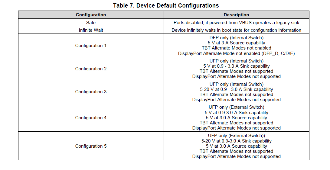
3.  Regarding the TPS65987D...

3.A . Is HRESET equivalent to removing VIN_3v3?  We want to be able to do a complete reset if the device locks up, faults, errors, etc.  Is HRESET good enough to reset the entire device or should I add a PFET to VIN_3V3?

3.B.  The external SPI EEPROM interface is intended for additional profiles so I included it in the board but I am planning on leaving it un-populated.  Are you aware of any cell phones that are not able to charge from the TPS65987D without an additional profile?  I would like to make sure that I am not leaving anyone out, so much as you are aware of today.

3.C.  I am replacing the push buttons of the POWER DUO SOURCE reference design with host processor GPIO.  Our board will only provide 5V or 9V, so I am planning on pulsing GPIO1 to enable 9V negotiation and if I need to force it back to 5V I will pulse HRESET.

3.C.1.   I am not planning on changing the default configuration, but if we do that I understand I may lose any changes when I reset the device to force it into 5V only mode.  Is there another way to put the controller back into 5V only mode other than resetting it?

3.C.2.  If I'm planning on using the configuration for the POWER DUO SOURCE reference design, should I leave the unused GPIOs floating or tie them to ground?  I am concerned that if they float, the device may go into unknown states.  The datasheet says to let GPIO 2 and GPIO5 float, but I don't really want to modify the profile - I would rather use the power duo source firmware you provide without modifying it.

Thank you in advance for your help,

Adam G.

  • Hello Adam,

    Find answers to your questions below

    1. If you add me as a friend here on E2E, you can send me a private message including the schematic for me to review

    2. Whether you use the TPS2546 or TPS2549 is up to you as both devices can be used for your design. The TPS2549 implements only divider 3 while the TPS2546 implements only divider 1 and 2. So its not that the TPS2549 implements an extra divider mode, it just implement one that is not offered on the TPS2546. Divider 1 is capable of 1A, Divider 2 is 2.1A, and divider 3 is 2.4A.

    3A. No, HRESET is not the equivalent of removing VIN_3V3 from our device. HRESET will reset our part, but it will not force us the re-download the patch bundle. Based on what you are wanting, HRESET will work perfectly fine and there's no need to implement a PFET

    3B. The default configurations should be compatible with any Type-C or Type-C PD compliant device. So to answer your question, I do not know of any devices off that are not compatible with our products.

    3C. If you are wanting to implement the same functionality as the Power Duo board, then you will need to populate an external flash.

    3C1. You could implement an extra app configuration to where it will go back to 5V. For example, with the power duo project file, it has 4 options of 5V, 9V, 15V, and 20V depending which button is pressed. For your project you could do 5V, 9V, and 5V

    3C2. Refer to the pin descriptions within the datasheet on how to handle unconnected pins.

  • Hi Adam,

    I sent you a friend request, thank you.  Your responses seem to answer my questions except 3.c.2. and only because I was planning on using the power duo source firmware and I expected it's behavior is not reflected by the datasheet.... In the power duo source board your switches are active high so I'm just going to pull them down.  This way, I can remove those resistors and let the pins float if I need to.

    Regarding the external flash and power duo implementation... All I really want is a 5V/9V USB PD compliant charging port that's cost conscious.  I didn't want to make my client pay for the EEPROMS, but they're cheap so this probably isn't a big deal... That said I also didn't want to charge them time to manipulate the configuration tool and come up with a custom app.... Do you recommend the 'easy' button is to use what you've already done with power duo source or is it easy enough to use the config tool and abandon the external EEPROM?  What I'm getting at is - would you expect a user needs to spend significant time in the config tool?  If the answer is yes, it can take a few days or more to set up the config and successfully flash the 65987D, then it probably makes more sense for me to just include the EEPROM for now and avoid a software task.  If making a custom configuration, flashing it and verifying it only takes a few hours then I'd prefer to abandon the EEPROM to lower the BOM cost.

    - Are there other drawbacks to running without the EEPROM as a USB PD source?

    I'll send you my schematic shortly. Thanks again for your help,

    Adam

  • The power duo functionality of changing the source/sink capabilities advertised is triggered on a rising edge. SO holding them low should be fine. However, I would not leave them floating as the PD controller could detect this as a transition if it floats to a certain threshold. The best thing to do is disable those GPIO's that you are not planning on using.

    We do not have any default configurations that advertise only 5V/9V, as well as implements the power duo app config so you will need to implement an external EEPROM. Both the power duo source and sink EVMs have their own external EEPROM. If your customer doesn't wish to use an EEPROM, then you can use one of the following default configurations, but none of them seem to line up with what you are wanting to accomplish.