This thread has been locked.

If you have a related question, please click the "Ask a related question" button in the top right corner. The newly created question will be automatically linked to this question.

TCAN1042H: Which parameter represents how many nodes the CAN device support ?

Part Number: TCAN1042H
Other Parts Discussed in Thread: SN65HVD251

Hi,

               My customer used to use TCAN1042H, but recently, they asked for a new device which can support more device through the CAN BUS. . Please kindly suggest which TI device can meet this requirement?

                 More information. : 1M datarate, 5M distance, only can support 20 nodes. their target is more than 32 nodes. 

                    1. is there any limitation or design consideration to support more nodes?

                    2. please recommend a  better device which can support more nodes.  

  • Hello Yue,

    Please refer to section 10.2.1 of the TCAN1042-Q1 datasheet.  

    Theoretically, the TCAN1042 is designed to support up to 100 nodes at once in a network.  However, the practical maximum number of nodes in a network can depend on multiple factors, including bus length, data rate, parasitic loading, network imbalances, etc.  The number of nodes supported becomes system-level design problem at that point.  

    I am curious why the customer is claiming that only 20 nodes are supported by the TCAN1042, given the system requirements that you have listed: 1Mbps data rate and 5m bus length.  Given these parameters, I don't see why the TCAN1042 would fail to support 32 nodes in the system.

    Can you provide more information about the network the customer is designing?  Information about network topology, stub lengths, placement of termination, etc. can be very helpful when analyzing this kind of problem.  

    Best Regards,
    Max Megee

    TI Transceiver Interface

  • Hi Megee,

    1. They used TCAN0142 in master station,  SN65HVD251 at slave station. 

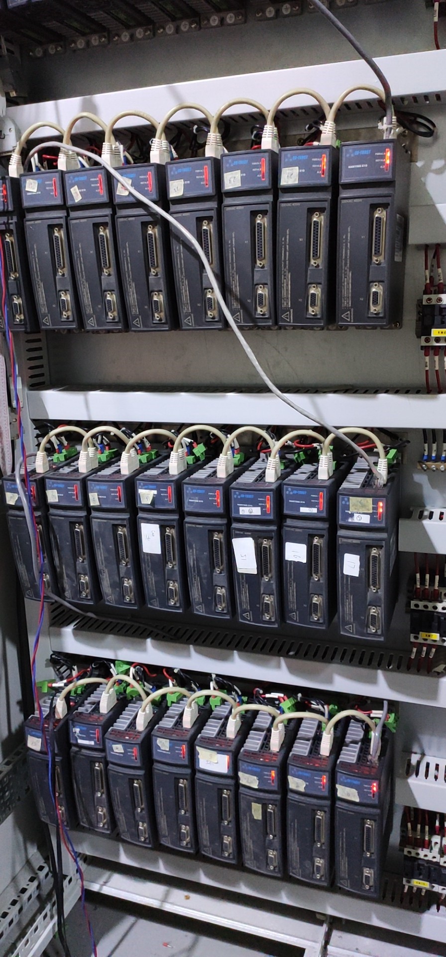
    2. About topology,stub length and placement, please see below picture. Stub length,according to my understand is 20cm 【the white line between each two device】

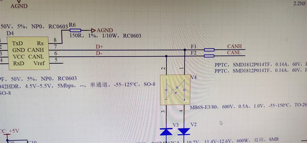
    3. part of the schematic

    4. About the Rterm, They used two 120Ω,one is at master station side, one is at the last slave station.  according to their recent test, added 3 more 120Ω at the last three slave station, some improvements can be made. but still cann't reach 32 nodes. 

    5. Also used SN65HVD251  at master side can have better performance on nodes numbers, but also less than 32 nodes. 

    Let me know if further information need. thanks. 

  • Any update here? thanks.

  • Hi Yue,

    Apologies on my delay.  

    This is an interesting issue.  My first thought is that this may be a loop delay timing issue on the CAN bus at 1Mbps.  Usually, adding more termination beyond the two 120-ohm resistors should hurt the signal integrity, since it lowers the VOD of the CAN signals by adding extra load.  In this case, though, it may serve to reduce the timing between bit states and thereby allow one or two extra nodes to be added to the bus.  

    When we think about system network design, we have to design the network and maximum data rate with the greatest system delay in mind.  The greatest delay is the total loop time from one end of the bus to the other.  This loop delay includes transceiver loop delay, cable delay, and any other series delay you may introduce to the CAN bus via isolators or other devices.  In this case, I think we can start with an estimate for just transceiver and cable delays together.

    Starting on the master side, we count on loop delay for the TCAN1042 (maximum 175ns).  The cable delay will be pretty small, since it is only ~6.5m maximum based upon your estimates from the picture above.  We give a rule of thumb for ~5ns/m of cable, so for a round-trip delay the cable portion can be estimated at around 65ns.  

    Since the customer is using the SN65HVD251 on the slave side, then they have the ability to control the loop delay of the transceiver via the Rs pin.  The datasheet gives three recommended settings: Rs connected to ground via a short, via a 10k resistor, and via a 100k resistor.  From the schematic that you included, it looks like the Rs pin is connected to ground via a 150-ohm resistor.  Can you confirm this value?  This should be fine, as it should put the transceiver loop delay somewhere in the range of 100-120ns.  That gives a total of ~360ns of round-trip delay, which should be no problem for this system to handle.

    Could you confirm the Rs pin setting for me on all nodes that use SN65HVD251?  If any of the nodes have a high resistance connection on Rs, then this may add too much loop delay into the system and disrupt the CAN protocol during arbitration or acknowledge.  

    If this isn't a timing issue on the CAN bus, then we will need to have a look at the CANH and CANL signals themselves.  Do you have any scope shots on the CANH, CANL, TXD, and RXD signals together?  This will help in the debug process since we have limited information right now as to what is going wrong in the communication.

    Best Regards,

    Max