This thread has been locked.

If you have a related question, please click the "Ask a related question" button in the top right corner. The newly created question will be automatically linked to this question.

Right connection to work LED as indicator

Part Number: TFP401


Hi team,

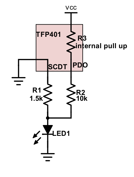
My customer want to do that turn on the IC when the IC is working and turn off the IC when the IC is not working.

Currently he has built the following schematic.

Is this connection OK to work as the customer want?

Best regards,

Koyo

  • Hello,

    I assume you mean "turn on the IC LED when the IC is working and turn off the IC LED when the IC is not working", right?

    In principle, the connection is fine.  However, I am not sure if the current going through the LED in this case will be sufficient to turn it on. Please check the LED spec to make sure.

    Regards,

    Yaser

  • You are correct, what I wanted to say was not IC but LED.

    My customer understood LED can be worked as you said (Vf=2.2V, If=20mA).

    I have another question.

    My customer want to know that PDO become Low if SCDT is Low (inactive).

    While SCDT is Low, the picture I showed first will be following picture as equivalent circuit.

    Customer guess TFP401 has pull up resistor between Vcc and PDO.

    Therefore my customer has concern PDO might not be Low state if R3 is smaller than R1+R2.

    Can you estimate the R3's value whether it is smaller than R1+R2?

    My customer want to do that PDO is Low when SCDT is Low.

    Best regards,

    Koyo

  • Hi Koyo,

    They can just connect SCDT and PDO directly, and then connect them to a small resistor in series with the LED. You can reference the DC Digital I/O Electrical Characteristics to get an idea of what resistor value is needed and the current capability.

    Regards,

    I.K.