This thread has been locked.

If you have a related question, please click the "Ask a related question" button in the top right corner. The newly created question will be automatically linked to this question.

TPS65987D: Uploading configuration over I2C

Part Number: TPS65987D


Hello,

I am writing to ask about configuration process of TPS65987D.

Setup description:

Our board is based on TIDA-01627. SPI_MISO is pulled up, ADCIN1 is in range 0.3 - 0.38

Behavior:

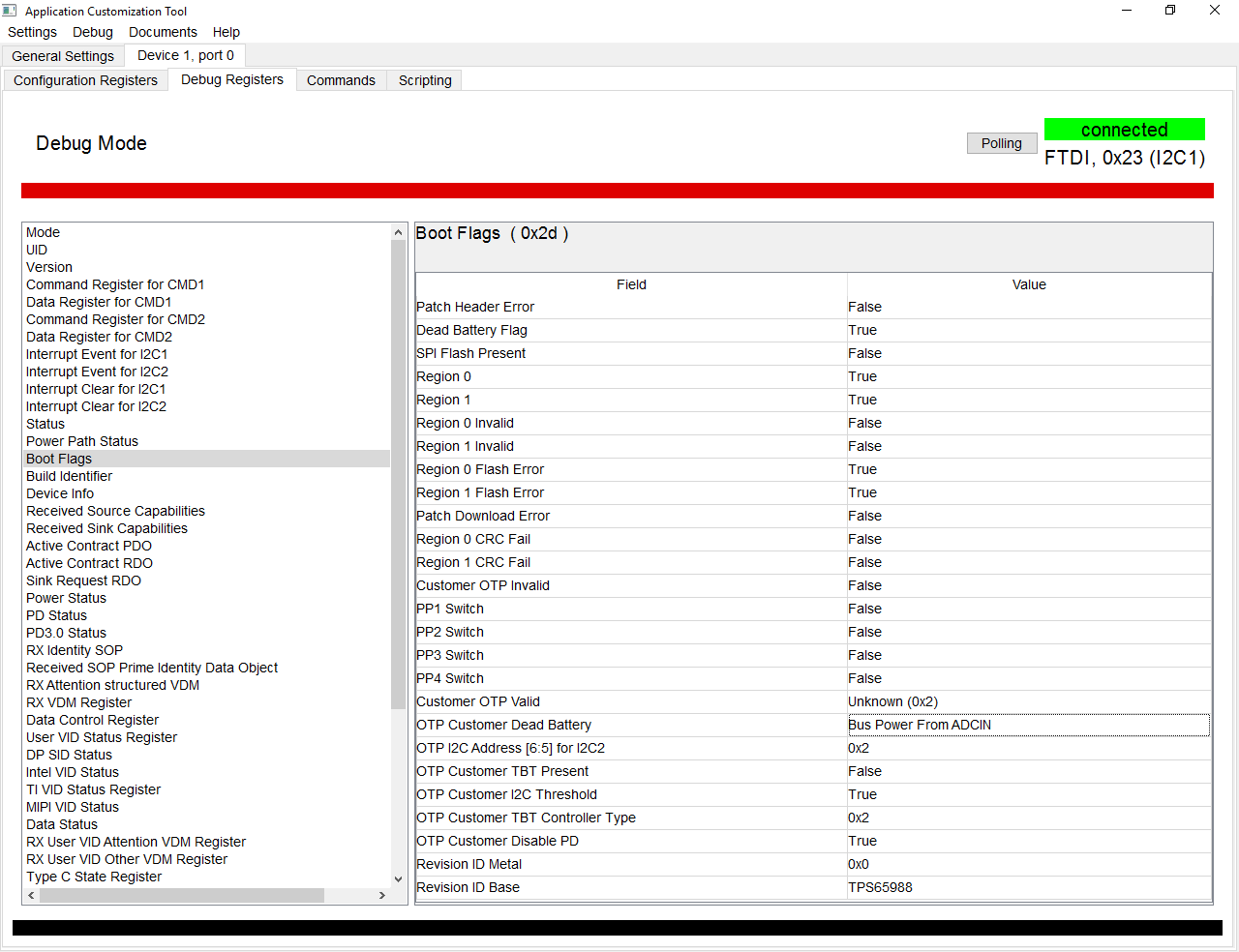
When powered from both VBUS or VIN, TPS65987D gives valid 3V3 output form LDO. There are no problems with communication

over I2C2. Reading 0x3 register gives output PTCH. Using 'Device -> Write config to Device(RAM Only)' tool gives output success.

Second reading of 0x3 register still gives output PTCH. Device never goes to APP mode. Issuing Gaid command do not work either.

My question is:

How do I put device in custom application mode? I would like to use I2C programming at first because it seems faster for checking different settings.

Best regards,

Wojciech

  • Hi Wojciech,

    If you would like to put the device in custom application mode without using a flash you will need an embedded controller to use I2C communication. For this you must create a Patch Bundle to provide the configuration to the device. I will recommend taking a look over the following lick. This link you open a pdf explaining how the communication over I2C must happen ( http://www.ti.com/lit/pdf/slva972 ). I hope this documentation guides you through the process. Thank you very much for using E2E.

    Regards,

    Francisco Lauzurique  

  • Hi Francisco,

    Thanks for response and sorry for not answering for such a long time.

    Based on your answer and the fact that I can not use Application Customization Tool to send a Patch Bundle directly to the device i decided to use an external flash. Can you write me if it is possible to write project to external flash by using Application Customization Tool and FTDI adapter? And if an answer is yes, how can I do that? I am using W25Q80DVSNIG flash.

    Best regards,

    Wojciech Maćkowiak

  • Hi Wojciech,

    The following document explains in detail the process using our GUI tool. http://www.ti.com/lit/pdf/slvub60 Let us know if this solves your thread.

    Thanks,

    Francisco Lauzurique

  • Hi Francisco,

    Thank you for link. After reading this document, I think, I am still doing something wrong.
    First I create new project: Project->New Project and choose: TPS65987DDH->Standard->DFP->None.
    Next Project->Save Project and Binary->Save Binary.
    Then: Change File to previously saved low region binary file.
    Here I use Device->Flash Firmware to Flash and I get SPI flash to Drive successful prompt.
    In the end I tried two things:
        - Power cycle
        - Issuing Warm reboot in debug mode

    To check if device was flashed in a correct way I check Port configuration register value in Debug Mode, but it is UFP not DFP.
    Can you write what is wrong with my way of configurating?

    Best regards,

    Wojciech Maćkowiak

  • Hi Wojciech Maćkowiak,

    Try this way:

    Project >  New Project > TPS65987DDH >  Standard > DFP > None > Binary > Full Flash Image (note: this is the choice required to save the binary)

    Then to  load binary:

    Binary > SPI Flash from Binary file

    I hope this helps. Let us know if this solves your thread. Thanks 

  • Hi Francisco,

    Sorry for not responding for such a long time.

    Using your method gives me Success output. Unfortunately TPS65987D still not starting in right configuration.

    Below adding output from Boot Flags register:

    As you can see TPS65987D do not see external flash despite the fact I am able to program memory using FTDI chip.

    Any ideas?

    Best regards

    Wojciech Maćkowiak

  • Hi,

    Can you share your project file and your binary file with me. I would like to do some testing. I tried the same process on my part and it was working as expected. You can also try to do a power cycle and see if the registers update.

    Regards,

    Francisco Lauzurique  

  • Hi,

    Thank you for your help. I managed to run TPS65987D chip.

    It seems that problem with comunication was made by faulty solder.

    Sorry for comotion and once again thank you for help.

    Best regards,

    Wojciech Maćkowiak