This thread has been locked.

If you have a related question, please click the "Ask a related question" button in the top right corner. The newly created question will be automatically linked to this question.

DP83822I: Normal Link Pulse duration / ~40ns instead of 100ns

Part Number: DP83822I

Hello everyone,

I am desperately trying to make two DP83822I work. They are both connected in RMII to one NXP i.MX6ULG2 and have the addresses 0x00 and 0x01. For the schematics, please contact me in private.

The MDIO interface seems to work fine, I can read all the registers and their reading seem OK. The PHYs are configured in RMII and are slave. The 50MHz is well sent from the CPU.

Nevertheless, auto-negotiation fails nearly all the time and I have no link (no led turned-on and no ping possible in u-boot). 

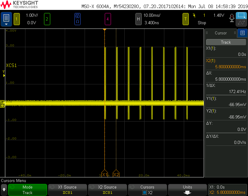
By looking at the signals, I see that the pulses I have for the negotiation a duration of ~40ns instead of 100ns and are repeated every 5.7ms instead of 16ms. It looks like the PHYs work in free-running mode (at 125MHz ?) but I don't know why that would happen. 

Here is a dump of the main registers (connected to an empty interface but similar values when connected to the network).

0x00 - 0x3000
0x01 - 0x7849
0x02 - 0x2000
0x03 - 0xa240
0x04 - 0x1e1
0x05 - 0x0
0x06 - 0x4
0x07 - 0x2001
0x08 - 0x0
0x09 - 0x0
0x0A - 0x100
0x0B - 0x1000
0x0C - 0x0
0x0D- 0x0
0x0E - 0x0
0x0F - 0x0
0x10 - 0x4002
0x11 - 0x108
0x12 - 0x0
0x13 - 0x800
0x14 - 0x0
0x15 - 0x0
0x16 - 0x100
0x17 - 0xe1
0x18 - 0x480
0x19 - 0x8001
0x1A - 0x0
0x1B - 0x7d
0x1C - 0x5ee
0x1D - 0x0
0x1E - 0x102
0x1F - 0x0

And some registers of the extended set:

0x0462 - 0x1
0x0463 - 0x0
0x0467 - 0xF70
0x0468 - 0x000

The overall shape of the pulse is good but the timing is wrong. 

Is there anything I could check to fix this issue ?

Regards,

Sébastien

  • Hi Sébastien,

    This can be due to any of the following:
    - Glitch on the power supply ramp
    - Glitch on Reset pulse
    - Un-optimized board layout causing noise coupling on the supply pins
    - Un-optimized 50MHz clock routing
    What is your VDDIO level? Can you read register 0x0421?
    Regards,
    Hung Nguyen
  • Hello,

    Thank you for your reply and sorry for my late answer, I was trying to get as much information as I could.

    So, about the layouts, I am pretty convinced that everything is fine. All the lines are routed with an impedance of 50ohm and length matched. The PHYs are really close to the CPU (~1cm) so it should not matter anyway.

    The VDDIO level is 3V3. About 0x0421, what I am supposed to find there ? (not documented). Is is part of the extended set or not ?

    For the reset and the supply, there was some interesting data. The reset is not well performed on my board. The 50MHz clock is provided to the PHYs (XI) by the CPU. The CPU and the PHYs have the exact same reset signal, so the XI is not present when the reset goes high. I changed that but it didn't help so much.

    About the ramp-up, the supplies are fine but I measured my 3.3V/Reset pin at 0.8V with an power supply OFF on my board!

    In fact, I have a FTDI cable connected to my board which injects current/voltage to the whole system when it's off via RX and TX. There was the culprit. If I remove the FTDI cable at startup, everything starts properly. If it's there at startup, PHYs are not properly working. I tried to sink current on my 3.3V supply and it starts to work with a "0V" state of 550mV. 

    So, it is OK now, the problem was not really linked to the PHYs (I guess there are more sensitive that other chips which work with the exact same voltage issue).