Hello. We are bringing up the custom board based on the NXP LS1046A. We have
4 x TI DP83867. 2 of them are using the SGMII and are connected as 1Gb and
those work correctly (at least simple ping / dhcp in U-Boot works).
The other 2 use RGMII and are connected as 100Mb (4 wires).
The U-Boot ti.c driver is used for the PHY:
source.codeaurora.org/.../ti.c
During the ping test, the RGMII interfaces fail at (when executed for the first
time):
```
=> ping 192.168.10.1
Using FM1@DTSEC3 device
ARP Retry count exceeded; starting again
ping failed; host 192.168.10.1 is not alive
```
and at (for consecutive executions):
```
=> ping 192.168.10.1
Using FM1@DTSEC3 device
FM1@DTSEC3: Tx error, txbd->status = 0x8800
FM1@DTSEC3: Tx buffer not ready, txbd->status = 0x8800
FM1@DTSEC3: Tx buffer not ready, txbd->status = 0x8800
FM1@DTSEC3: Tx buffer not ready, txbd->status = 0x8800
ARP Retry count exceeded; starting again
ping failed; host 192.168.10.1 is not alive
```
The MDIO communication with the chip works flawlessly. The RGMII mode and PHY
addresses are verified.
For the test purpose, we have prepared isolated network. We have the 100Mb-capable
link partner connected on the other end. We have the ability dump the packets on the other
end, but we were unable to send a single packet via the RGMII interfaces yet.
We have tried the far-end reverse loopback on the MII inside the PHY and the
packets sent from the link partner were being received back.
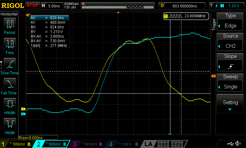
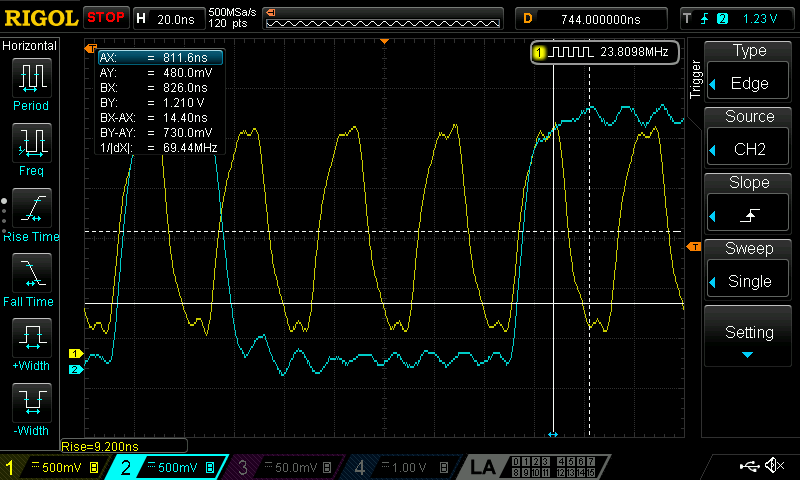
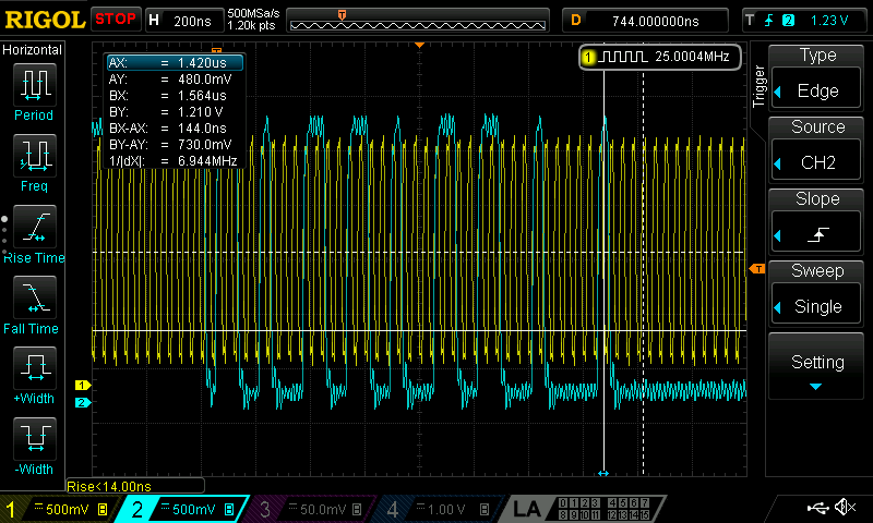
I suspect the issue is on the MAC-PHY RGMII interface.
We have tried various TX_DELAY values with no success.
We have checked that the RGMII mode is enabled:
* STRAP_STS1 (0x0e) register:
```
=> mii write 0 000d 001f
=> mii write 0 000e 006e
=> mii write 0 000d 401f
=> mii read 0 000e
0000
```
- RGMII strapped to enable (bit 12 is 0)
- SGMII strapped to disable (bit 11 is 0)
- address is 0x0 (bits 0:1)
* PHYCR (0x10) register
```
mii write 0 000d 001f
mii write 0 000e 0010
mii write 0 000d 401f
mii read 0 000e
4040
```
- SGMII is disabled (bit 11 is 0)
* RGMIICTL (0x32) register
```
mii write 0 000d 001f
mii write 0 000e 0032
mii write 0 000d 401f
mii read 0 000e
00D3
```
- RGMII is enabled (bit 7 is 1)
* 0x6f register dump:
=> mii write 0 000d 001f
=> mii write 0 000e 006f
=> mii write 0 000d 401f
=> mii read 0 e
0000
Standard registers:
* 0x00 - 0x1f registers dump:
```
=> mii read 0 0-1f
addr=00 reg=00 data=1140
addr=00 reg=01 data=796D
addr=00 reg=02 data=2000
addr=00 reg=03 data=A231
addr=00 reg=04 data=01E1
addr=00 reg=05 data=C1E1
addr=00 reg=06 data=006F
addr=00 reg=07 data=2001
addr=00 reg=08 data=6801
addr=00 reg=09 data=0200
addr=00 reg=0a data=0C00
addr=00 reg=0b data=0000
addr=00 reg=0c data=0000
addr=00 reg=0d data=0000
addr=00 reg=0e data=0000
addr=00 reg=0f data=3000
addr=00 reg=10 data=4040
addr=00 reg=11 data=7C02
addr=00 reg=12 data=0000
addr=00 reg=13 data=9C40
addr=00 reg=14 data=29C7
addr=00 reg=15 data=0000
addr=00 reg=16 data=0000
addr=00 reg=17 data=0040
addr=00 reg=18 data=6150
addr=00 reg=19 data=4444
addr=00 reg=1a data=0002
addr=00 reg=1b data=0000
addr=00 reg=1c data=0000
addr=00 reg=1d data=0000
addr=00 reg=1e data=0002
addr=00 reg=1f data=0000
```
From the register 0x11 we can verify that the autonegotiated speed is 100Mb.
From the registers 0x0/0x1 we can see that the autonegotiation is enabled and
that the link is up. The link LED is also active.
Any more hints how to approach this problem are welcome.
Thanks
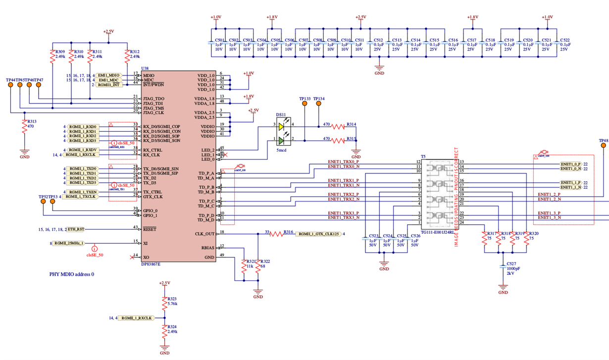
Attached is the relevant page from schematics for one of the RGMII interfaces:
-
Ask a related question
What is a related question?A related question is a question created from another question. When the related question is created, it will be automatically linked to the original question.


