This thread has been locked.

If you have a related question, please click the "Ask a related question" button in the top right corner. The newly created question will be automatically linked to this question.

DS90UB954-Q1: DS90UB954 CSI has no output.

Part Number: DS90UB954-Q1

Hi Team,

My Customer is using 954&913A. The current situation is as follows:

BC channel can respond normally.

Sensor end has data output.

913 has data input.

Do not know how to test FC signal.

The sensor data is YUV422, using RAW10 high 8 bits.

Register configuration is as follows (Address on the left and register value on the right):

x1 0xff

0x4c 0x1
0x58 0x58

i2cset -f -y ${I2C_BUS_NUM} ${primary_devaddr_7bit} ${SER_ALIAS_ID_ADDR} ${REMOTE_SER_ADDR_8BIT}
i2cset -f -y ${I2C_BUS_NUM} ${primary_devaddr_7bit} ${SLAVE_ID0_ADDR} ${AR0144_ADDR_8BIT}
i2cset -f -y ${I2C_BUS_NUM} ${primary_devaddr_7bit} ${SLAVE_ALIAS_ID0_ADDR} ${AR0144_ADDR_8BIT}

0x6D 0x7F

0x70 0x1E //RAW10 ID
0x71 0x1E //RAW10 ID

0x7C 0x80

0xc 0x1
0x33 0x3

0x20 0x20
0x1F 0x03

Could you help customers check the register configuration?

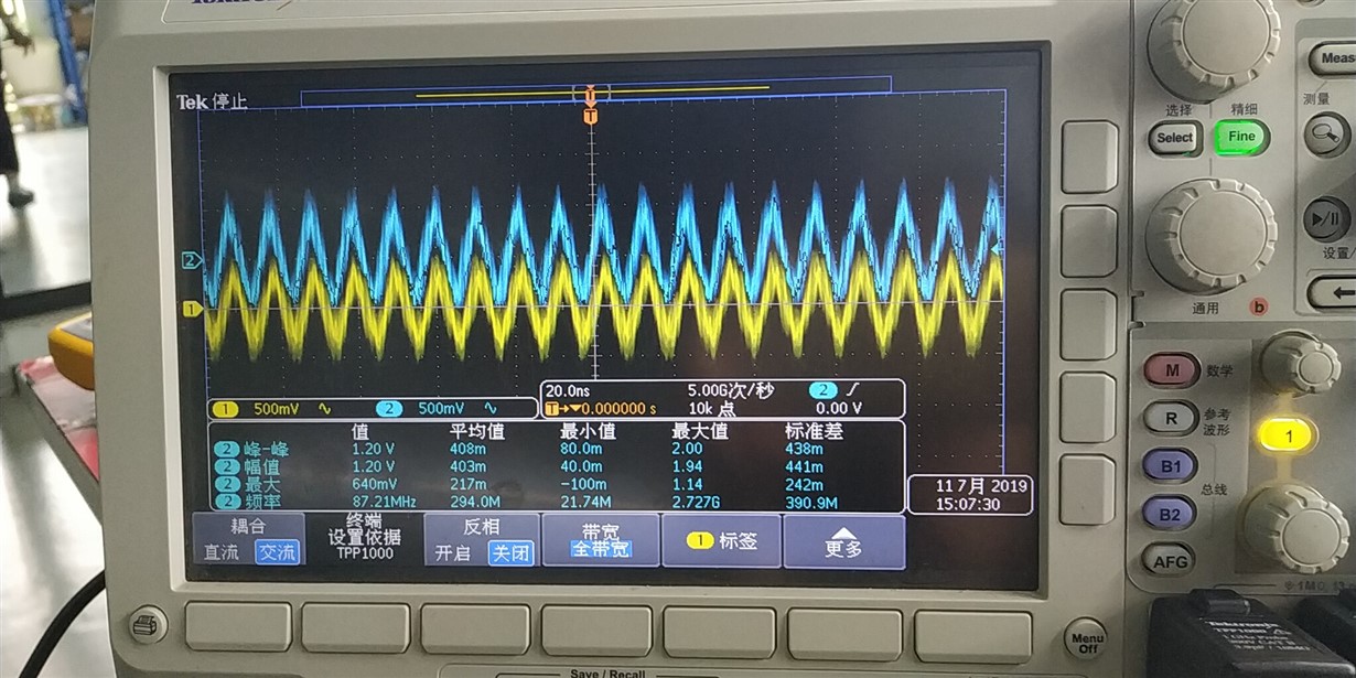
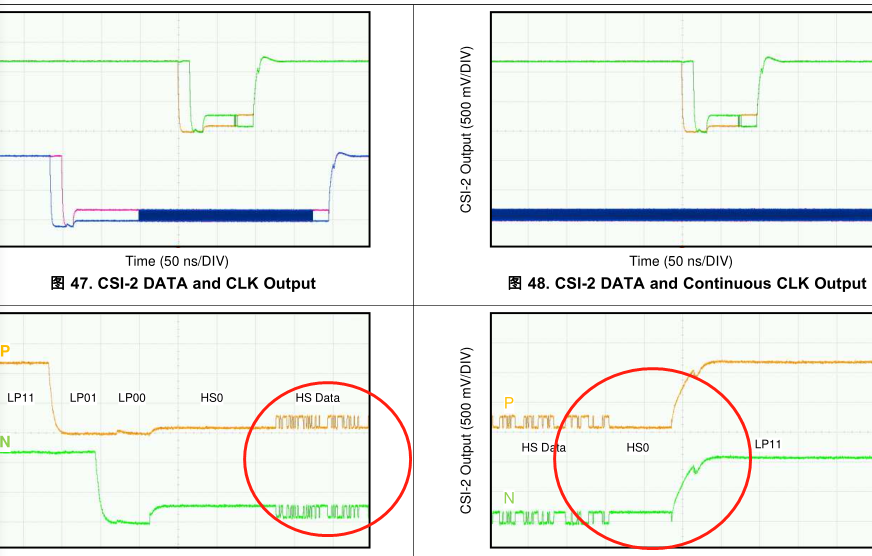
The waveform of CSI output is inconsistent with the datasheet. The measured clock and data waveforms are as follows:

Customers need the following support:

1. Confirm whether there is any problem with the configuration of CSI end and port and whether there is a lack of configuration. If there are any questions, help me point out and revise them.

2. Is the measured waveform normal?

  • Hello Amy,

    The scope and probe being used to measure the CSI signals does not seem appropriate for the speed. If you are using continuous clock mode you can probe the clock deferentially, but you need a much higher speed scope/probe since the waveform looks very distorted. I would suggest at least a 2GHz-4GHz scope/probe for these signals. 

    For the data, in order to match the waveform in the datasheet, you must probe the P/N signals of one of the data lanes with each one single-ended to GND. This is because DPHY uses dynamic terminations, so the signals switch between single ended and differential periodically. 

    Best Regards,

    Casey 

  • Casey,

    Thank you very much for your reply.

    Could you help me confirm that the customer's configuration is correct? Now the customer is not sure whether it is caused by hardware configuration or software configuration.( 4lan, continuous clock, YUV4222 RAW10 high 10 bit, port 0, remote 913, local 954, remote 913 have normal input).

    At present, BC is normal. It can control and read remote 913, but there is no output at the CSI end.

    At present, the amount of the chip used by the customer company is relatively large, and the customer is more anxious about this project. Hope to get your help as soon as possible.

    Regard,

    Amy

  • Hello Amy,

    Firstly it does seem that there is some sort of CSI-2 output from the 954, although it may not be correct as per your expectations.

    I see a few issues:

    - For register 0x0C, please ensure bit 7 stays high as per the register default 

    - The CSI transmitter speed (0x1F) should not be changed while the transmitter is enabled. Please change the speed before enabling the CSI output in register 0x33

    - If operating at 400Mbps/lane (as per your 0x1F setting), there are additional steps to ensure proper CSI-2 timings. These programming steps are shown in section 7.4.21 of the datasheet and should be programmed after setting 0x1F but before setting 0x33. 

    Best Regards,

    Casey