This thread has been locked.

If you have a related question, please click the "Ask a related question" button in the top right corner. The newly created question will be automatically linked to this question.

DS90UB948-Q1: how to set up the devices when using the MAP tool

Part Number: DS90UB948-Q1
Other Parts Discussed in Thread: DS90UB949-Q1, USB2ANY, , ALP, DS90UH948-Q1

Dear team,

My customer wants to use MAP tool, but we can't connect successfully. The computer connects the one side of the USB2ANY, and USB2ANY's other side connects the DS90UB948-Q1, and DS90UB948-Q1 connect the DS90UB949-Q1 through the cable as below the first picture. But the computer always show no detection as below the second picture.

Could you please tell me the reason? Do you have any documents to introduce how to set up the device?

Thanks & Best Regards,

Sherry

  • Hello Sherry,

    We will look into this and respond back today. 

    Best Regards,

    Casey 

  • Hi Casey,

    That problem has been solved. Now we encounter a new problem as below, I use the 948&949, but the information on the right box is 926. In addition, there is no margin analysis box.

    Thanks & Best Regards,

    Sherry

  • Sherry,

    This happens if ALP is not getting response from the board and the device ID read from the board does not match the selected profile (Ux948). Please check power and jumpers. Also, check if the I2C communication setup is proper.

    By the way, please make sure you have latest ALP framework (v1.57) installed and also download and update to latest profiles using ALP-PROFILE-UPDATE. You can find both from TI.com

    http://www.ti.com/tool/ALP

    Thanks,

    Vishy

  • Hi Vishy,

    Thanks for your reply!

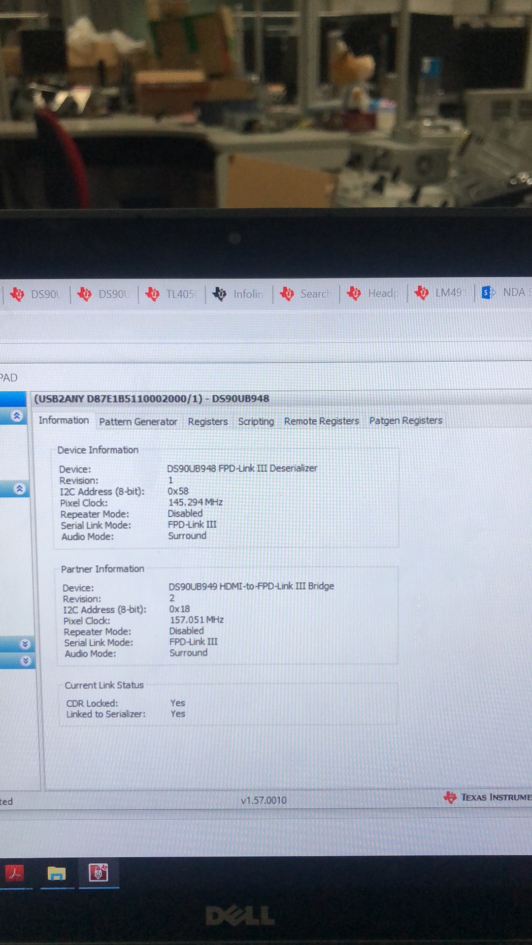
    Yes, when I disconnect the I2C connection between MCU and 948 on customer's board, it works as below,

    But this interface doesn't have the Margin Analysis tab, the interface in the user guide is as below, I don't know why my interface is different form below interface. I have updated the ALP to the latest version. Could you please tell me which step do I miss?

    Thanks & Best Regards,

    Sherry

  • Sherry,

    As I mentioned above you also have to download ALP-PROFILE-UPDATE from TI.com. Please see picture below

    Quit ALP if it is running. Dowload above ALP-PROFILE-UPDATE. It's a zip file. Extract the installer and go through the installation steps. It will update 948 profile to the latest version that supports Margin Analysis.

    After installation restart ALP and check Help -> About this Program. You should see built date as "April 26, 2019"

    Thanks,

    Vishy

  • Hi Vishy,

    Thanks for your help! It works, but we still have some questions about this tool as below,

    1.The USB2ANY tool is connected to the IIC communication line of the deserialization chip (hereinafter 948 is an example). What is the connection sequence? Should I connect USB2ANY first and then power on the 948 to initialize(method 1), or disconnect the IIC communication after the onboard MCU completes the 948 initialization through IIC communication, and then connect with the USB2ANY IIC(method 2)? The two connection methods have different simulation results. The first picture is method 1, and the second picture is method 2. Which one is correct?

    2. For MAP tool emulation, what are the requirements for the transmiission data of SerDes? General communication (customer-defined data stream) or dedicated data format for simulation testing?

    3.What effect do the two settings(6 Bufer delay and 0 Bufer delay) have on the signal analysis results? Which setting results are more accurate?

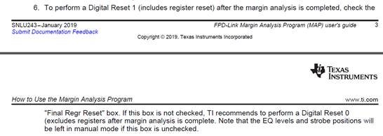
    4. I don't quite understand the following instructions for Final Regr Reset. How is the Reset0 operation implemented? If the Final Regr Reset dialog box is selected, is all register values reset to the original values, regardless of whether the register values were manually modified multiple times before?

    5. Regarding the EQ/SP End setting in the ALP tool, is the ALP tool automatically adapting the EQ/SP start range after ALP recognizes the currently connected device? Or still need to manually adjust according to the connected device?

    6. The DWELL parameter has an effect on the simulation results. The longer the selection time, the more theoretically the results are, but we need to wait longer. Can we recommend a DWELL time parameter that is effective enough and does not have to be the maximum? Below first picture is 1000ms DWELL, and the second picture is 10000ms DWELL.

    7. Regarding the output result of MAP, under the same SETUP (physical connection and ALP setting) conditions, the results obtained by multiple simulations are inconsistent. Is there any link missing or wrong?  same setup, the first picture is the first test result, and the second picture is the second test result.

    8. What types of signal connection problems are included in the red box in the MAP analysis results? Can I choose to add/delete? In the EXCEL report, the red box NG part has different numbers, such as 0.3, 0.9. What do these numbers mean?

    9. The 948 has two input simulations, which get different EQ/SP OK settings, and are not completely related. How to choose the appropriate EQ/SP settings and meet the requirements of both LANEs?  The first picture is RIN0, and RIN0 can select EQ=9/10/11,SP=6/7/8/9. The second picture is RIN1 which is different from the RIN0.

    10. Does the link evaluated by the MAP tool contain only the link between the SerDes, or can it contain the quality of other interface signals from the SOC output to 949?

    Thanks & Best Regards,

    Sherry
  • 1. Method 2 is correct

    2. MAP tool will setup the SERDES device and sweep over strobe/eq settings to test the link. No custom data streaming needed. Internal lock establishment and monitoring procedure takes care of it.

    3. That extra buffer delay option is not available in Ux948 Device. Please ignore that.

    4.If final register reset option selected, after running margin analysis a digital reset (including registers) of the device is done. Value 0x02 is written to Ux948 device register 0x01.

    I will come back to you on the other questions soon.

    Thanks,

    Vishy

  • 5. When "Start Margin Analysis" button is pressed, tool disables adaptive EQ. Then device is configured for manual EQ and sweeps over the selected strobe and eq range while monitors lock. Then it updates the Margin Analysis Status window with the result. 

    6. Yes if you increase the dwell time it would take a longer time to sweep. To begin 1000ms is sufficient. Compared to adaptive EQ where maximum (for 954 device is about 100ms), it is already 10x. Once you know the green range, you can set the sweep area to the green EQ/SP range and double dwell time to see if there is any change to the green range.

    7.Method 2 should give you consistent results. When sweeping, the margin analysis program is repeatedly modifying the SERDES registers and monitoring for lock and status bits. So disable any SOC access or setup.

    8. Red box indicates loss of lock or errors. After the selected dwell time, lock and errors are repeatedly monitored. If there is no failure (10/10) you get a green box. If it fails 9/10 times, you get red (in the saved file 0.9) and so on.

    10. Map tool is only for the link between the SERDES.

    I will come back to you on Q9 soon. 

    Thanks,

    Vishy

  • I checked about Q9. Device has AEQ controls per port. So basically registers are duplicated for each port. Please refer DS90UH948-Q1 Data Sheet Section 8.3.3. If PORT1_SEL in register 0x34 is set, port 1 AEQ controls are selected.

    Thanks,

    Vishy

  • Hi Vishy,

    I still have some questions as below,

    1. How to choose the appropriate EQ/SP level based on the simulation results. My customer's concern is whether the fixed value can adapt to the changing electrical environment of the car after selecting a fixed EQ/SP, as well as factors such as line aging. For example, the simulation results of 948 below,
    Which EQ/SP value is recommended? Not only can it meet the laboratory conditions, but also the real car environment.

    2.If we choose the AEQ, at what time does the chip complete the AEQ process? For example, is the system powered on every time, or in real time during the work process?

    3. If we choose the AEQ, the device will set the EQ level automatically. And I want to know adaptive equalization is achieved by detecting what signal?

    If we use the MAP tools, we will use a fixed EQ/SP level , so now we should suggest the customer not to use the AEQ but use the fixed EQ/SP level ?

    Thanks & Best Regards,

    Sherry

  • 1. How to choose the appropriate EQ/SP level based on the simulation results. My customer's concern is whether the fixed value can adapt to the changing electrical environment of the car after selecting a fixed EQ/SP, as well as factors such as line aging. For example, the simulation results of 948 below,
    Which EQ/SP value is recommended?

    This is explained in the app note SNLA301, page 8. You get min/max EQ and min/max SP from MAP as explained there and program it to the min/max registers. Then device will search and adapt only within the above set min/max selections. So it's not a fixed value but an area limited by the min/max selection.

    2.If we choose the AEQ, at what time does the chip complete the AEQ process? For example, is the system powered on every time, or in real time during the work process?

    As explained above, you program min/max limits. Device will search for lock only within the selected bounds (known green area). Every time system is powered, as part of initialization min/max limits have to be programmed and then device will search and lock. Search for lock always start from the min. If it loses lock, it will increment and look for the next valid lock. You have more stable lock at the center of the green area than at the edges where it can loose lock. 

    3. If we choose the AEQ, the device will set the EQ level automatically. And I want to know adaptive equalization is achieved by detecting what signal?

    As explained above, you choose min/max based area so device can search for stable lock in the selected area by checking the received signal.

  • Hi Vishy,

    Yes, I see the SNLA301, page 8, but I still don't know how to choose fixed EQ/SP value. Below picture the green area is too large, and I don't know how to choose the appropriate fixed value. You mean I need to choose the center value, so the appropriate value is the value marked by the yellow box below, right?

    Thanks & Best Regards,

    Sherry

  • Sherry

           Suggest you choose AEQ. AEQ completion and completion of adaptation of the overall system is indicated by LOCK signal going up. AEQ is always adapting, especially to changing conditions in a car. 

    Thanks

    Vijay