This thread has been locked.

If you have a related question, please click the "Ask a related question" button in the top right corner. The newly created question will be automatically linked to this question.

DS90UB953-Q1: Issue with camera capture/streaming, interfaced over FPD Link 3

Part Number: DS90UB953-Q1

Hi,

We have interfaced Snapdragon 820 to OV2311 over TI FPD Link 3 based SerDes (DS90UB953-DS90UB960) and we are facing issue in the captured preview as attached. We see blue yellow lines that become more prominent,the darker the capturing (room) environment becomes. 
We suspected noise introduced due to SerDes or timing issue in programming SerDes. But when we enabled sensor test patterns, we are not observing these lines.
When OV2311 is interfaced directly over MiPi CSI, for the same configurations for sensor and 820, we don't see this issue. Basically there is no change between direct MiPi CSI and over SerDes, except SerDes configurations at init time.
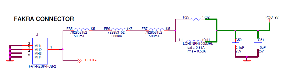
SInce there is PoC in our design so our first suspect was that, tried isolating power and data lines but still no conclusion. Attached snapshot of POC filter also, please let me know for your suggestions.
Please provide some input on the attached noise. What could be the source of it?


  • Hi Shubham,

    The PoC network looks good to me. 

    Could you tell me the values of the following registers and let me know if you see any errors detected by our device?

    953 Error Registers:


    Register

    Types of Errors

    Comments

    0x52

    Status

    0x52[1]: back channel (CRC) error detected

    0x52[0]: back channel link detected

    0x56,0x55

    CRC

    0x56: upper 8 bits of CRC error count

    0x55: lower 8 bits of CRC error count

    Reset CRC error counter by setting 0x49[3] = 1

    0x5C

    CSI Error

    indicates number of CSI packets with errors

    0x5D-0x60

    CSI Error

    indicates various CSI errors

    0x61

    CSI Packet Header

    0x61[7:6] indicates VC ID from imager

    0x61[5:0] indicates data ID

    0x62-0x63

    CSI Payload

    If value 0x00, no incoming CSI data


    960 Error Registers:


    Register

    Types of Errors

    Comments

    0x4D

    Status

    0x4D[5]: indicates CRC (BC) error detected

    0x4D[2]: indicates parity (FC) error detected

    0x4D[0]: indicates whether there's lock

    0x4E

    Status

    0x4E[5]: indicates encoder error detected

    0x4E[4]: indicates buffer error detected

    0x4E[3]: indicates CSI error detected

    0x54

    CSI Error Flag

    flags different CSI errors

    0x56,0x55

    Parity

    0x56: upper 8 bits of parity error count

    0x55: lower 8 bits of parity error count

    0x7A

    CSI Error

    indicates various CSI errors

    0x7B

    CSI Error

    indicates number of CSI packets with errors

    Best,

    Jiashow

  • Hi Jiashow,
    Thanks for your suggestions.
    Following are the error registers values for Live stream from Sensor:.
    Serializer:
    Reg: 0x52 Val:0x45 (HS_PLL_LOCK, LINK_DET, RX_LOCK_DETECT)
    Reg: 0x55 Val:0x0 (CRC_ERR_CNT1)
    Reg: 0x56 Val:0x0
    Reg: 0x5c Val:0x2
    Reg: 0x5d Val:0x0
    Reg: 0x5e Val:0x46 
    Reg: 0x5f Val:0x0
    Reg: 0x60 Val:0x0
    Reg: 0x61 Val:0x0
    Reg: 0x62 Val:0x0
    Reg: 0x63 Val:0x7

    Deserializer:
    Reg: 0x4d Val:0x13 
    Reg: 0x4e Val:0x4
    Reg: 0x54 Val:0x0
    Reg: 0x55 Val:0x0
    Reg: 0x56 Val:0x0
    Reg: 0x7a Val:0x0
    Reg: 0x7b Val:0x0
    Following are the values of error registers for Test Pattern from Sensor
    Serializer:
    Reg: 0x52 Val:0x45
    Reg: 0x55 Val:0x0
    Reg: 0x56 Val:0x0
    Reg: 0x5c Val:0x0
    Reg: 0x5d Val:0x0
    Reg: 0x5e Val:0x0
    Reg: 0x5f Val:0x0
    Reg: 0x60 Val:0x0
    Reg: 0x61 Val:0x2b
    Reg: 0x62 Val:0xd0
    Reg: 0x63 Val:0x7

    Deserializer:
    Reg: 0x4d Val:0x3
    Reg: 0x4e Val:0x4
    Reg: 0x54 Val:0x0
    Reg: 0x55 Val:0x0
    Reg: 0x56 Val:0x0
    Reg: 0x7a Val:0x0
    Reg: 0x7b Val:0x0
    As we pointed out above, there is no issue seen from color pattern(rolling or stationery) from Sensor. It is only when we enable Analog circuitry(that is live capture) that we face issue. What could be the cause for (Lane 0: Control Error in HS Request Mode, Lane 0: Multi-bit Error in SYNC Sequence - Uncorrectable, Lane 1: Multi-bit Error in SYNC Sequence - Uncorrectable) in the case of live capture? Why are they not seen in sensor test pattern?
  • Hi Shubham,

    From the registers/values you provided, there's no parity/back channel errors detected, which means there's no issues with the link itself. The 953 is detecting CSI errors from its CSI receiver. How's the layout of your board on the CSI input side (impedance, skew matching, crosstalk, etc.)? It might also be worth it for you to consult the imager manufacturer about this.

    Best,

    Jiashow