This thread has been locked.

If you have a related question, please click the "Ask a related question" button in the top right corner. The newly created question will be automatically linked to this question.

SN65LV1224B: No Locking on Sync or Random data with loopback from SN65LV1023A

Part Number: SN65LV1224B
Other Parts Discussed in Thread: SN65LV1023A, , SCAN921224

Hi,

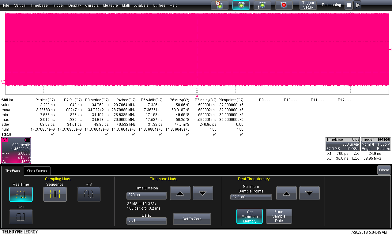
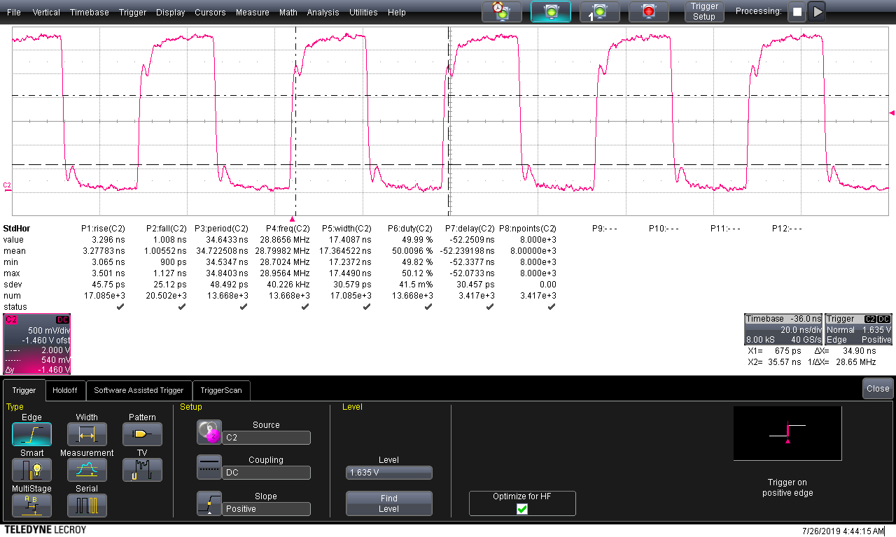
The SN65LV1224B and SN65LV1023A are located on the same PCB and receive their RefClk's from two separate FPGA IO's sourced by a embedded PLL. The frequency is 28M8Hz.

In the connection between both devices is a 33ohm resistor in each signal line at the transmitter side and one 100ohm between the + and - signal lines at the receiver side.

When I use a loop back cable the SN65LV1224B is not able to lock. 

Adding the differential probe (Lecroy WL-PLink + D830 and DXX30-SP) connected to the Teledyne/Lecroy SDA 808Zi-A scope, the SN65LV1224B locks and transmitted data is correct received. Even when the scope is switched OFF but still connected to the mains, the lock remains and received data is equal to the transmitted. When the probe is disconnected from the scope and held to GND of the board everything remains working correct.

What could be the problem? 

The reference clocks seem to be OK, because locking is possible.

The transmitted SN65LV1023A data is correct. When connected to a DS92LV1212A, the device locks and passes the data correctly.

On the previous version of the board the serializer: DS92LV1021A and deserializer: DS92LV1212A were used without any problems.

Thx

  • Hi bart,

    Since you used the previous versions of these devices before, have you referenced this application note? http://www.ti.com/lit/an/slla435/slla435.pdf

    The TCLK and REFCLK on the 1023A/1224B are a lot more sensitive than the previous iterations. The tolerance is +/- 100 ppm.

    Regards,

    I.K. 

  • Hello I.K.

    Yes, I have but only when I reported problems with the new combination.

    I think the problem is not caused by the ref clock. Because the connected differential probe doesn't influence the ref clock signal 

    There must be something else causing the not locking when the probe is removed.

    Regards, Bart

  • Hi Bart,

    I believe the first thing to check is still if both clocks are within +/-100ppm, as that is the main issue we've seen that causes the deserializer to not lock.

    It is strange that connecting a differential probe enables the deserializer to lock though. The only thing the probe does is add additional loading (e.g. capacitance) to the signal. Can you get an eye diagram and check the signal integrity at the deseriailzer input?

    Regards,

    I.K. 

  • Hello I.K.

    I have checked the clock and input signal. 

    The ref clock freq is 28M8Hz. The 28.8 MHz >> 34.72 nsec *1e6 >> 34.72 usec / 100 = 3.472 usec. I used the Lecroy SDA808Zi-A with a time base of 320usec/div. The 320usec/div gives: max: 29.0666MHz min: 28.6389MHz measured over 14.376648e6 cycles. (see first picture) This is within the 100ppm: max: 29.088MHz min 28.512MHz 

    Locking to the ref clock @ 20nsec/div, gives the following max and min values: 28.9564MHz and 28.7024MHz, measured over 13.668e3 cycles. (see second picture)

    The eye pattern based on the SYNC option in the serializer is given in third picture measured ver 10.096k cycles and timebase 10nsec/div. The cursors give position in the signal and in the eye pattern based on the neg edge trigger pulse smaller 3.5 nsec. A longer timebase 50.0nsec/div is presented in forth picture. 

    The last (5th) picture gives the last eye pattern set-up with the refclock.

    I only raise a question mark on the ringing on the edges of the ref clock. It seams not to be an issue because the locking when the probe is active. Also the ringing at the positive edge does not cross the 2V again and for the negative edge the 0.8V is not crossed causing false clocks.

    What be done to achieve the lock without the differential probe?

    Regards, Bart

    First picture

    Second picture

    Third picture

    Forth picture

    Fifth picture

  • Hi Bart,

    The frequency tolerance is actually calculated as 28.8 MHz * 100/(1e6) = 0.0028. So, the max should be 28.80 MHz, and the minimum is 28.797 MHz. Your refclk is outside of datasheet specification. Additionally, can you do the same measurement for the TCLK on the serializer side to see if it's within specification? Your third picture also looks strange. Those artifacts in the middle of the openings would cause issues for the receiver.  

    Nonetheless, to achieve lock, you should try and get both clocks within 100 ppm. Since the clocks are coming from an FPGA, it may be difficult to do that. As an alternative, you can try replace the deserializer with the SCAN921224. It is functionally the same as the DS92LV1212A except with added JTAG capability that you can ignore, but the package and pinout are unfortunately not the same. However, since you were able to achieve lock with the DS92LV1212A you will also achieve lock with the SCAN921224.

    Regards,

    I.K.