This thread has been locked.

If you have a related question, please click the "Ask a related question" button in the top right corner. The newly created question will be automatically linked to this question.

PCA9544A: CONFIGURE THE I2C ADDRESS FOR BQ28Z610 SLAVES

Part Number: PCA9544A
Other Parts Discussed in Thread: BQ28Z610,

Hi,

We have a custom board with 3 BQ28Z610 fuel gauges attached to PCA9544A channel 0, 1 and 2. We had established the I2C commands used for the PCA9544A when we connect one fuel gauge directly to the I2C line bypassing the PCA9544A (see link for I2C comm for PCA9544A : https://e2e.ti.com/support/power-management/f/196/p/814131/3028325#3028325).

Our I2C is running on 100Khz, standard mode. We has used the following format for the I2C mux slave address: 0xE0 + <values of A2-A0> + R/W as per Section 9 of the datasheet.

For I2C channel 0, the Hardware Selectable bits are: A2=0, A1=0, A0=0.

For I2C channel 1, the Hardware Selectable bits are: A2=0, A1=0, A0=1.

For I2C channel 2, the Hardware Selectable bits are: A2=0, A1=1, A0=0.

Using the I2C command protocol for the BQ28Z610  fuel gauge at channel 0, we issued an I2C write with I2C address = 0x30 and the transmitted data is exactly the same as suggested in the BQ28Z610 documents. We had then tried to read one of the registers of BQ28Z610 by issuing an I2C Read with I2C address = 0x31 but we read back a wrong register content. (i.e. attempt to read chem ID, expected value = 0x2158 but we read 0xF0F0).

Are we using the correct protocol format for the I2C mux or should we issue additional commands prior to attempting to read and write to the slave devices?

Thanks,

Kat

  • Hey Kat,

    "For I2C channel 0, the Hardware Selectable bits are: A2=0, A1=0, A0=0.

    For I2C channel 1, the Hardware Selectable bits are: A2=0, A1=0, A0=1.

    For I2C channel 2, the Hardware Selectable bits are: A2=0, A1=1, A0=0."

    From what you are saying here it sounds like you are changing the actual physical address of the I2C device. Typically (probably 99 percent of applications) you would not change the hardware selectable bits after the device powers up. Normally they are hardtied to a pull up or pull down resistor. To enable a channel you would write to the I2C address (you would know this from the static bits plus the hardware selected bits you set before power up. From there you would then write the command byte to enable the channel.

    Example:

    1) Send PCA9544A address [ACK]
    2) Send Command Byte to turn on Channel 0 [0x04h] [ACK]
    3) [stop condition]
    4) Talk to your BQ device on channel 0
    5) repeat steps 1-4 but step 2 do channel 1 instead of 0

    -Bobby

  • Hi Bobby,

    Our custom board, has 4.7k pull up resistor for the SCL and the SDA lines. It also has 10k pull up resistor on the INTx lines. The Hardware bits were set to 011 (A2, A1, A0). We are also using the HAL I2C driver of the MCU. We are using I2C standard mode 100 kbit/s.

    We had followed your steps with our custom board. . After writing 0x04, we had attempted to read back. In summary, this is our process flow:

    1. Master listens to I2C line to verify if a slave address is detected.

    2. Once the I2C Mux slave address 0xE6 is detected, issue an I2C Write 0x04 to select channel 0.

    3. Delay 1s

    4. Attempt to read using slave address 0xE7. However, we were not able to read back anything.

    After issuing an I2C Write to 0xE6 with data 0x04, the I2C mux became unresponsive. We had tried to scan the I2C line again and our MCU was not able to detect the I2C Mux.

    When we reboot the whole board and attempt to scan the I2C line for any slave, we were able to detect the I2C MUX however, whenever we write 0x04, our I2C master does not detect the I2C MUX anymore.

    Is there any commands we should write to the I2C MUX before writing the 0x04? 

    Thanks,

    Kat

  • Hey Kat,

    7 bit I2C addresses do not have the upper (Most Significant Byte) go over decimal 7. So a slave address of 0xE6 is not possible. Assuming you GND the MUX's selectable pins, the slave address should be 0x70h. In your example, your MUX's A2-A0 pins are 011 thus the address is 0x73h.

    "Once the I2C Mux slave address 0xE6 is detected, issue an I2C Write 0x04 to select channel 0."

    Can you send scopeshots of SDA and SCL (in the same scope window overlapping) of your I2C write to the I2C MUX and then one probing at channel 0 (or whatever you have enabled) with SDA/SCL trying to talk to the BQ device?

    "Is there any commands we should write to the I2C MUX before writing the 0x04? "

    It should just be the slave address (write bit) followed by the command byte 0x04h.

    -Bobby

  • Hi Bobby,

    We had tried using 0x73 however we were not getting any response from the I2C Mux. It is our understanding that the slave address format is 

    We had the A2:A0 as 011 and since we were writing to the I2C Mux, we added 0 for the Write bit. Thus our LSB is 0110. Whenever we try to communicate with the 0xE6 and send 0x04 to select ch0, we were able to see signals on both I2C in pins and I2C out pins at Ch0. Thus we assumed that we are using the correct I2C Slave address.

    Furthermore, although we were able to verify that we were able to send signal to CH0, we were not able to read the correct Fuel gauge data. When writing and reading the I2C slave at CH0, do we need to follow any I2C Mux protocol? For example, in reading the CHEM ID of the  fuel gauge without using the I2C MUX, our protocol includes:

    1. I2C write to 0xAA(Fuel Gauge I2C Slave Address with Write bit): 0x3E2100

    2. I2C Write to 0xAA (Fuel Gauge I2C Slave Address with Write bit): 0x3E0600

    3. I2C Read from 0xAB (Fuel Gauge I2C Slave Address with Read bit): 0x3E

    Since we are using I2C MUX, should we append 0xAA before we issue our commands? Are there any protocols we should follow or any I2C MUX register we should manipulate before sending data to the Fuel Gauge at CH0?

    Thanks,

    Kat

  • Hey Kat,

    You should provide an o-scope shot of the I2C read from '0xAB'. With this we would be able to tell if the I2C transaction is correct (Do pull ups look okay, signal integrity in tack? VoLs look okay? Any unexpected non monotonic behavior? Oscillations in the signal? Undershoots which can break devices? Overshoots which can break devices? I2C pull up voltages losing regulation? There is A LOT that an oscope shot can show which a logic analyzer does not show.), or if the battery gauge requires extra steps inorder to properly read.

    My guess here is that you are only reading one byte of data when you need to read 3 bytes. Essentially your I2C master doesn't ACK to the slave to tell it to read further bytes.

    You may also need to resend the command byte to reset the pointer for the battery gauge to the correct address as I assume it uses an auto increment function. I can assign one of the battery gauge Applications Engineers to this thread to help trouble shoot this as I specialize in the I2C MUX device and not the BQ devices.

    "Since we are using I2C MUX, should we append 0xAA before we issue our commands? re there any protocols we should follow or any I2C MUX register we should manipulate before sending data to the Fuel Gauge at CH0?"

    No, if the channel is enabled then the I2C MUX's job is done. You now just need to figure out the correct way to talk to the fuel Gauge.

    -Bobby

  • Hi Kat,

    This got rotated to gauges. If you are talking to the gauge at address 0xAA, it will respond.

  • Hi Bobby and Batt,

    I think there might be some confusion here. As I've stated before, we have no problems with communicating with the fuel gauge when we used it directly as an I2c slave without using the I2c mux. Our main concern is simple, what is the protocol format when writing and reading to a slave address via the i2c mux?

    We know we need to use the I2C Mux address and in our case, it's 0xE6 as we were previously advised to use 0x73 but apparently, using the advised address does not give us any signal on channel 0. We had written 0x04 to address 0xE6 to enable channel 0. The question we have, which is not evident on the I2c mux data sheet, is how do we communicate with an I2C slave address?

    Should we send <i2c mux address> <ch select on control register><ch0 slave address><data> in one single transmission?

    I do apologize if I'm sounding a bit exasperated  here but this is our second TI chip for this project and me and my team had been frustrated with the documentation and miscommunication with the support of the 2 ICs we are using from TI.

  • Hey Kat,

    "We know we need to use the I2C Mux address and in our case, it's 0xE6 as we were previously advised to use 0x73 but apparently, using the advised address does not give us any signal on channel 0. We had written 0x04 to address 0xE6 to enable channel 0. The question we have, which is not evident on the I2c mux data sheet, is how do we communicate with an I2C slave address?"

    Technically, the correct way to do this is to use 0x73h as the slave address because I2C slave addresses do not go above 0x7Fh for 7 bit addressing. Your master/code seems to ignore the I2C slave address format and instead requires the byte to read and write to a slave (this is non standard).

    The correct way to write to the PCA9544A is shown in figure 7:

    Where the I2C transaction begins with a (1) start condition, next you (2) send the slave address [I2C standard dictates the slave address follows the start condition and is 7 bits long where the upper part of the byte is restricted to 111 as a maximum value for 7 bit addressing and the bit after the address is the Read/Write bit, Again this is the correct way to perform an I2C transaction as stated by the I2C standard for 7 bit address slaves]. (3) If the slave recognizes it's address and the transaction is valid then you will receive an ACK after the read/write bit is sent. The next byte is used to configure the slave, (4) send the slave byte which you require to enable the channel of the device, keep in mind this is a true MUX meaning you can only select one channel at a time and not multiple like the I2C switches can do. (5) if the slave recognizes the sent byte, then it will ACK. (6) After the slave ACKs, initiate a stop condition, At this point the I2C MUX will enable the channel that was selected in parenthesis '4.'

    Refer to table 1 for channel section where bit 2 is the enable bit and the lower bits are channel select bits (like a MUX):

    "Should we send <i2c mux address> <ch select on control register><ch0 slave address><data> in one single transmission?"

    transaction 1: [start condition] I2C MUX ADDRESS [ACK] --> ch select on control register [ACK] --> (STOP)

    transaction 2: [start condition] ch0 slave address [ACK] --> (if slave has multiple registers send pointer byte otherwise send data)  [ACK] --> If finished, NACK and send stop condition

    Everything underlined above is controlled by the I2C master, ACKs are controlled by the slave and are indicators of received messages for write transactions.

    In your case, it sounds like you need to use 0xE6 to send the slave address (this is non standard) because your software/code does not format the I2C transaction for slave addresses. You can confirm whether or not this is true by looking at an o-scope shot of the SDA/SCL where you will see the MSB sent first and the 9th clock cycle either ACK to what you sent or NACK to show the slave did not recognize its own address.

    You do need more than 1 transaction because the I2C MUX REQUIRES a stop condition to enable the channel. You would be able to see this as a NACK when sending the CH0 slave address on a o-scope shot because the MUX did not enable the channel until the stop condition occured.

  • Closed, unless reopened by Kat. Operation doesn't concern gauge.

  • Hi Bobby,

    We had tried sending the fuel gauge commands using the sequence you had stated above. After sending the commands, we are supposed to read the values from the fuel gauge however, our board hangs up and becomes unresponsive. For the reading sequence, we had the following i2C commands:

    transaction 1: I2C MUX ADDRESS(0xE6) --> ch select on control register 

    transaction 2: CH0 slave read address--> read 36 bytes

    We then had the first 5 bytes of the read 36 bytes displayed in the hyperterminal. Without using the I2C Mux, the Fuel Gauge commands were working and returns expected results displayed in the HyperTerminal. However, using the I2C MUX, our board hangs up and becomes unresponsive. It did not displayed anything in the HyperTerminal. Are we using the correct I2C read command sequence?

    Thanks,

    Kat

  • Kat,

    "However, using the I2C MUX, our board hangs up and becomes unresponsive. It did not displayed anything in the HyperTerminal. Are we using the correct I2C read command sequence?"

    The sequence sounds correct and the fact that you can read 5 bytes seems like it works (at first). It sounds like there may be a signal integrity issue if your board hangs up. Maybe a stuck bus due to a false clock edge somewhere in the interaction. Are you able to provide a schematic for the I2C MUX and scopeshots of the 5 read bytes?

    -Bobby

  • Hi Bobby,

    I had attached here the summary of our tests including an excerpt of our schematic. We had been keeping track of all the tests we had conducted and summarized them in this document. None of the tests gave us the expected result.

    I2C Mux Testing_Rev00.pptx

  • Hey Kat,

    Thanks for the additional information.

    My comments:

    The rise times on the clock lines for both the slave and master seem to be slow, I would recommend changing the pull up resistors to a lower value as of right now, we are likely violating the rise time limit defined by the I2C/SMbus spec. Your power point looks like you are using 4.7k pull ups, we may want o try 2ks or even 1ks for clock and data.

    You may also want to get rid of the 22 ohm series resistor as that is shifting up the VoL on your signals.

    On test 3 of your power point:

    I can see that the device see's its address and it does Acknowledge the address. The read value looks like you wrote 0xX4h which should enable channel 0. Were the Pink and Green probes connected to Ch0 or channel 2? The second slide seems to indicate that we could be probably the wrong channel and should be probing channel 0.

    This waveform shows when you try to send slave address 0x55h and perform a write, you get a NACK. The slave channels below show the signal may not actually reach 70% of Vcc due to the weak pull up resistors, the bus is too capacitive and the pull ups are too weak to drive the clock signals high enough to hit ~70% of Vcc. The slave device essentially may not be seeing the clock pulses because of this. I'd suggest strengthening the pull up resistors.

    Please change the pull up resistors and get rid of the series resistors and resend the scopeshots if you are still seeing problems.

    -Bobby

  • Hi Bobby,

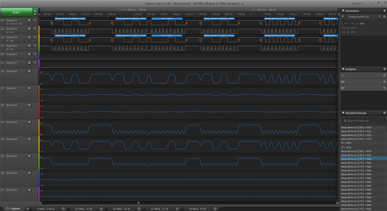
    We had probed the Master I2C line to the I2C Mux. We are attempting to read the CH2 thus we sent out 6 on the Control Register of the I2C Mux. At the same time, we had also probed the CH2 I2C lines. See image below:

    Based on our captured image, we have the following observations:

    1. We had followed the instructions provided to us in this thread.

    2. We were able to see that we had successfully switched the channel due to the I2C ACK after sending 0x06 to the I2C Mux Address (210 in decimal or 0xE6).

    3. We were also advised that once we were able to set the channel, we can communicate directly to the I2C slave without any added protocol syntax. Thus we had attempted to write commands to Slave 170 (0xAA) for the Fuel Gauge Write Address. This function is working without the I2C MUX.

    4. Based on the graph and the behavior of our DUT, we are receiving NACK. 

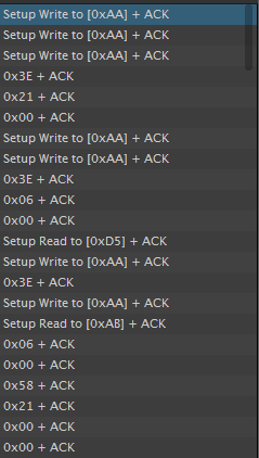
    Using the same Fuel Gauge as slave address, we had bypassed the I2C MUX and connected it directly to the Master I2C BUS. We were able to write and read from the Fuel Gauge I2C Slave:

    With the tests we conducted, the NACK only occurs when we use the I2C MUX. What else can we do to ensure that the I2C Slave ACK when using the I2C MUX?

    Thanks,

    Kat

  • Kathleen Gayo said:

    Hi Bobby,

    We had probed the Master I2C line to the I2C Mux. We are attempting to read the CH2 thus we sent out 6 on the Control Register of the I2C Mux. At the same time, we had also probed the CH2 I2C lines. See image below:

    Ch3 and Ch5 I assume are the clock lines before and after our device. The shots here seem low, have the pull up resistors on both sides of our device been adjusted? To me this looks like the clock lines are not going above ~70% of Vcc still.


    Based on our captured image, we have the following observations:

    1. We had followed the instructions provided to us in this thread.

    2. We were able to see that we had successfully switched the channel due to the I2C ACK after sending 0x06 to the I2C Mux Address (210 in decimal or 0xE6).

    3. We were also advised that once we were able to set the channel, we can communicate directly to the I2C slave without any added protocol syntax. Thus we had attempted to write commands to Slave 170 (0xAA) for the Fuel Gauge Write Address. This function is working without the I2C MUX.

    4. Based on the graph and the behavior of our DUT, we are receiving NACK. 

    Using the same Fuel Gauge as slave address, we had bypassed the I2C MUX and connected it directly to the Master I2C BUS. We were able to write and read from the Fuel Gauge I2C Slave:

    With the tests we conducted, the NACK only occurs when we use the I2C MUX. What else can we do to ensure that the I2C Slave ACK when using the I2C MUX?

    Can you provide the schematic for the BQ device (I only want the I2C schematic from Channel 2 of our device to the SDA/SCL pins of the BQ device). I see that the recommended suggestion in the BQ datasheet shows 2x 100 ohm resistors in series with the device SDA/SCL lines. This can cause issues with the VOL shifts in the I2C lines in certain situations. If you have any series resistors on the line, I would suggest shorting them.

    I would also prefer o-scope shots as opposed to a logic analyzer because the scope shots show us more of what the signal is actually doing than a logic analyzer.

    Thanks,

    Kat

  • Hi Bobby,

    The Ch3 and Ch5 are the clock lines before and after the I2C Mux. The pull ups were changed to 1.3K as well.

    Regarding the schematic of the battery with the fuel gauge, I can only show a portion of it here as we have an NDA with the company who designed the battery packs. These are the limiting resistors used for the fuel gauge:

    One notable thing that we had kept mentioning before as well, is that whenever we connect the same battery with the fuel gauge directly on the Master I2C line bypassing the I2C MUX, the fuel gauge is able to ACK the commands. However whenever we use the I2C MUX, we kept receiving NACK. By simple deduction and eliminating the I2C MUX, we can conclude that the code for writing and reading directly to the fuel gauge works and that the fuel gauge in the battery pack is responsive thus, we don't think there could be a problem with the battery pack schematic. Currently, the main culprit for the NACK is the I2C MUX. We highly suspect that we may be sending incorrect I2C MUX command sequence or there may be a command the we need to issue first.

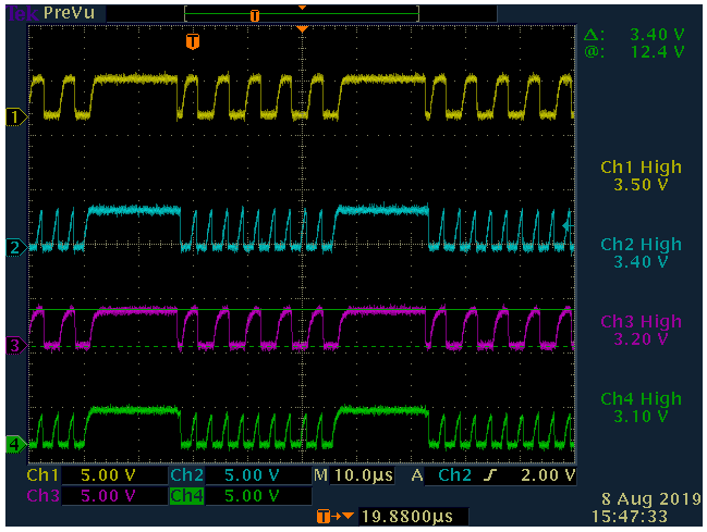
    This is the oscilloscope reading using the same DUT:

    Thanks,

    Kat

  • Hey Kat,

    Just for clarity, can you confirm my understanding of the I2C bus is correct? (If anything at all is wrong, please point it out) If the pink probe is correct, it would be best to probe to the right of R26 directly at the Bq device.

    Where Rx sits can make a difference (if its to the left of R25 or to the right of R26).

    "One notable thing that we had kept mentioning before as well, is that whenever we connect the same battery with the fuel gauge directly on the Master I2C line bypassing the I2C MUX, the fuel gauge is able to ACK the commands. However whenever we use the I2C MUX, we kept receiving NACK."

    The only difference this actually makes is the parasitic RDSon of the I2C MUX. When you enable the channel all you have between SDA and SD2 is an NFET and some ESD cells. If bypassing the MUX is what solves the problem then the issue is likely the parasitic Ron of the MUX.

    Otherwise this leads me to think that the issue stems from some kind of wrong set up. (Common problem I see is SDA and SCL are swapped on the secondary channels).

    1) Can you triple check to see if the SD2 of our device goes to SDA of the BQ device? (Use a DMM to do a continuity check on the PCB and also look at the schematic)

    Your I2C transaction looks good. 0x55h is the BQ's address

    2) Can you measure the rise time of the green waveform on one of the clock rising edges? Measure from 30% of Vcc to 70%. If we are operating at 400kHz, then we need to have a rise time faster than 300ns to be Smbus/I2C compliant. Your time divisions in the scope shot indicate one clock cycle is 2.5us thus 400kHz so this should be our target.

    Also an alternative approach, is it possible for you to ship a unit to us? I may be able to try to troubleshoot the unit here. (i'd only be interested in our I2C mux and the BQ device on the PCB so all other silicon could be removed from the bus.

    Thanks,

    -Bobby

  • Hi Bobby,

    We are trying to review the I2C mux connections and we had the INT pins floating in our schematic. Just a quick question, does the INT pins have any effect in writing/reading to the I2C Slave connected in the I2C MUX? What should be the polarity of our I2C MUX INT pins? Also, all our I2C Slave devices have no interrupt pinout. 

  • Hey Kat,

    "we had the INT pins floating in our schematic. Just a quick question, does the INT pins have any effect in writing/reading to the I2C Slave connected in the I2C MUX?"

    It shouldn't. It will just add additional consumption current from the device because the input stage of the device can float and partially bias the CMOS structure to cause shoot through currents. It has no affect on the SDA/SCL pins or the secondary channels.

    "What should be the polarity of our I2C MUX INT pins?"

    A pull up resistor would work, it could also be a pull down resistor. It doesn't really matter since it looks like you aren't using/relying on the INT output. You can leave the main INT pin floating (the one without a number)

    "Also, all our I2C Slave devices have no interrupt pinout. "

    That's fine. These pins don't have to be used. Referencing them to  Vcc is suggested in the datasheet though (GND is okay too).

    -Bobby

  • Hi Bobby,

    We will be sending a board to our US engineers. Can someone from TI support him locally in Mckinney/Plano, Texas?

    Thanks,

    Kat

  • Hey Kat,

    We should be able to support you in that location. Can you email me at duynguyen@ti.com? We can hash out the details on where and when offline.

    Thanks,

    -Bobby