Hello,
I have issues I fail to explain regarding CDR lock with DS125DF1610. Here is my setup: a SERDES link between two FPGAs with a DS125DF1610 between the two.
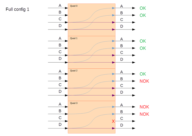
The DS125DF1610 crosspoint switch is setup this way (subject to change during process, but the initial setup is causing issues to begin with):

At first I wanted to limit the channels allowed to acquire lock (using shared registers 0x0F and 0x10) to the ones I needed, being channels A and B (TX) on each quad.
First issue: I soon realised that in order for the CDR to lock, for each channel, I had to allow lock for both the TX channel and the RX channel. That led me to allow all channels to lock except channel C in quad 3 (full config 1).

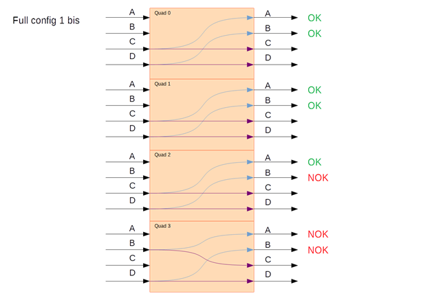
I then experienced a second issue here in quad 3: While every channel was locked and every link was working fine, somehow, turning off signal on the source of channel D RX caused the channel B TX to lose CDR lock and signal detect (as expected) but also caused channel A TX to lose CDR lock, while signal detect was still up. Signal was not modified on channel B RX. I noticed the problem was solved if I allowed channel C to lock, resetting shared registers 0x0F and 0x10 to their default values of 0xF (config 1 bis). I did not understand why, but the problem was solved. Moving on.

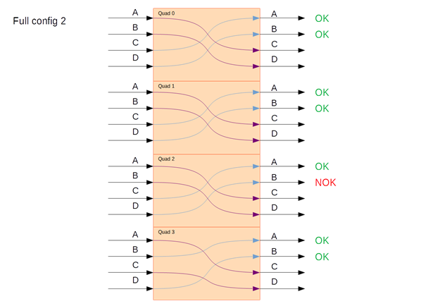
The initial setup worked, all channels were locked, all the links worked. The third issue arised when I turned signal off and then on again on the sources of all RX channels: All channels relocked successfully except channels A and B of quad 3. Channel B of quad 2 also had trouble relocking, but not systematically. I suspected a problem with the broadcast function of the crosspoint in DS125DF1610 and tried full config 2, in which each RX channel is routed to one TX channel only.

That solved the problem on quad 3 channels, again without me understanding why. The fourth issue remained though, being channel B TX of quad 2 frequently (but not always) failing to relock when signal is turned off and on again on the source of channel C RX. I tried playing again with the channels allowed to lock, with the allowed concurrent lock limit (shared register 0x05[3:0]), with the crosspoint parameters (local and multi-drive buffer, master/slave function...), with the EQ boost parameters like suggested on the related thread on this forum (tried CLTE adapt mode 1 instead of 0, then went back to 0 and tried a few EQ boost values), to no avail. At this point I don't understand what's going on and I have run out of options to try.
To rule out other causes for that issue, I also did this test: for channel B TX of quad 2, setting the FIR filter input on raw data instead of standard retimed data (channel register 0x1E[7:5] set to 0b000 while register 0x09[5] is set to 1). The signal being too weak this way for the receiving FPGA, I amplified it with the FIR filter MAIN, PRE and POST cursor taps (channel registers 0x3D, 0x3E and 0x3F set respectively to 0x3F, 0x49 and 0xD5). I know, this is ugly, not reliable, and I am certainly not keeping that setup permanently. But it allowed me to restore a functional link while the CDR of channel B TX of quad 3 was unlocked.
I am using a 25MHz reference clock daisy chained through 8 DS125DF1610 (has always been successfully locked), 10.3125 Gbps bitrate, no CLTE adaptation (EQ boost is set manually and kept still), no DFE. Polarity is inverted on channel B TX of quad 3 only.
I met these issues on several boards, leading me to rule out a hardware failure. The fact that the link is working properly on occasion seems to indicate that there is nothing wrong with the boards or the routing. I am pretty sure I am missing something in the way to set DS125DF1610, or I am failing to understand something in how it is supposed to work. Am I doing something wrong here?
Regards,
--
Romain Ducaffy


