This thread has been locked.

If you have a related question, please click the "Ask a related question" button in the top right corner. The newly created question will be automatically linked to this question.

SN75LVCP600: Function of EQ

Part Number: SN75LVCP600

Hi,

I have a quesiton. The SN75LVCP600 has tow inputs:

  • DE
  • DE = 0 à -0dB De-Emphasis
  • DE = 1 à -1.4dB De-Emphasis
  • EQ
  • EQ = 0 à +7dB
  • EQ = 1 à +14dB

The datasheet shows some combination of trace length and IC settings. Unfortunately not for the case DE=0 and EQ=1. What is the reason for that?

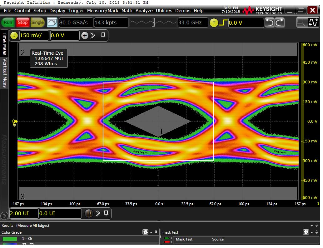
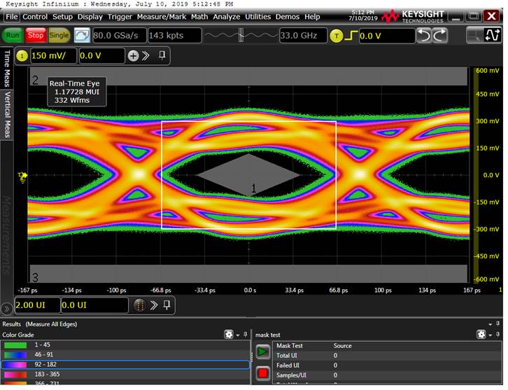
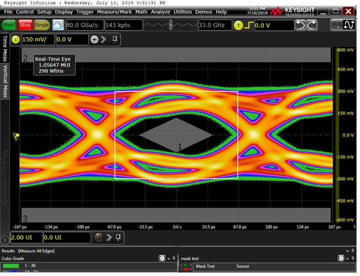
The compliance measurements does not show a difference if EQ=0 or 1 (see pictures below). A little bit more gain would help not to hit the eye.

Best regards, Xaver

  • Hi Xaver,

    The pictures do look very similar. The overshoot in the lower picture is slightly more pronounced - this may be due to the higher EQ setting.  Overall they do show some distortion in the eye wall which may be due to a reflection on the output side of the device.

    There are some waveforms on page 15 with EQ=1 in the datasheet.  The waveform with DE=0 should just have slightly higher output amplitude since the de-emphasis has been removed.

    Do you have waveforms which show the difference between DE=0 and DE=1 in your application?

    Regards,

    Lee

  • Hello Lee,

    I'm Andreas and from me are these measurements originally. In the pics below you see the difference between D=0/1. This difference is signifikant.

    EQ=0 (+7dB); D=0 (+0dB)

    EQ=0 (+7dB), D=1 (-1.2dB)

    Regards,

    Andreas

  • see below the influence of D in the application.

    EQ = 0 (+7dB); D=1 (0dB)

    EQ = 0 (+7dB); D=1 (-1.4dB)

    Regards

  • Hi Xaver,

    Thanks for the additional data with DE = -1.4dB.  The change in waveshape seems to show the output losses between the SN75LVCP600 output and scope are relatively low. 

    The typical VOD for DE=0 is ~ 600mV which is consistent with your scope data.  There is significant noise present on the upper and lower levels of the eye.  Is there something in the layout between the SN75LVCP600 output and the scope which is causing a reflection and reducing the eye height?

    Regards,

    Lee

  • Hello Lee,

    following topology has this net:

                 3.35mm 10n  1.17mm          31.98mm

    -----------|        ||           |-----|             |----------

    SN75LV  TX | -------||-----------| 0R  |------------ | RX HOST

    -----------|        ||           |-----|             |----------

    The 0R Resistor is a strap option, there is a second 0402 0R resistor as direct neighbor (<1mm).

    Best Regards,

    Andreas Kaeberlein


  • Hi Andreas,

    The capacitor and/or strap option are two areas to investigate.

    AC coupling capacitor:

    1. Is very close to the Tx pin so reflections do not have much time or space to attenuate and can show up in the output waveform.

    To overcome this issue it is recommend to use 0402 or small body size capacitors and add GND relief (in the form of a cutout) directly under the capacitor.

    2. Resistor Strap Option:

    This is a nice option to have, but often results in stubs between the signal a resistor if not executed perfectly. The best implementations generally share a pad with the AC coupling capacitor which is not needed if the strapping option is exercised.

    Regards,

    Lee

  • Andreas:

      any update?

  • Closing the E2E thread.  Please update the information and data regarding the device and channel layout if there are additional questions.

    Regards,

    Lee