This thread has been locked.

If you have a related question, please click the "Ask a related question" button in the top right corner. The newly created question will be automatically linked to this question.

AM26LS32A: Pullup resistor

Part Number: AM26LS32A

Hi team,

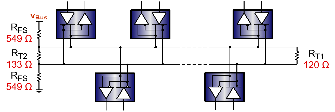
My customer would like to add the pull up resistor on all input and output pin. 

Is there any issue by adding pullup resistor?

Also, could you tell me the output status when the input is shorted? The input is always High by pullup resistor...

Regards,

Yoshi

  • Takahashi-san,

    In modern RS-485 transceivers and differential line receivers/drivers, there are biasing circuits that allow a known output when the differential inputs are shorted, open, or idle. This device doesn't include that, so when the inputs are shorted, the output is indeterminate. 

    One solution to this that is used in applications using older RS-485 (or RS-485 compliant) transceivers is external failsafe biasing. External failsafe biasing is a termination network for the differential bus that help with noise immunity, but also give a defined state in bus fault conditions (idle, open, or short). Typically this network is only placed at one node, and the pull-up and pull-down resistors are sized to match the characteristic impedance.

    All that being said, adding pull-up resistors on the output is okay as well. The output driver can driver a maximum of 8mA for the logic low level, so you'll have to size the pull-up resistor so the output can drive a logic low without "fighting" against the pull-up voltage.

    In short, you can use pull-ups on the inputs and outputs, but the termination network I show above is much more effective for the input, for several reasons.

    Please let me know if you have any other questions or concerns.

    Regards,

  • Hi Eric,

    Thanks for your quick reply. I understood. 

    Output of the modern transceivers and old transceivers with network resistor are High when the input is disconnect.


    The customer would like to detect whether wire disconnection. Is there any solution to detect the wire disconnection?

    Regards,

    Yoshi

  • Takahashi-san,

    This is a bit difficult to detect. In transceivers for bus fault detection is integrated (some CAN transceivers), a current detection circuit is used to know if the bus pins have been shorted together, to the supply, or to GND. 

    Something similar could be done with RS-485, having some kind of voltage or current detection circuit on the bus and note any changes when the bus is connected vs. disconnected. The problem with this approach is you'd have to know where the bus could physically disconnect (like the connector of a cable harness). Otherwise, you'll see the same voltage/current due to the external failsafe biasing always being present. The other problem with this approach is the detection circuit would have to be fairly fine resolution.

    Detecting an open using the controller is a more reasonable and cost-effective approach in stead of trying it on the transceiver side, in my opinion. An open on the bus to the transceiver just looks like an extended idle state. In the controller software, a timer could be set any time the bus goes idle, and based on the length of time, it could be assumed that a disconnect has happened. This would be very specific from application to application though, since "extended idle state" is subjective.

    Please let me know if you have any other questions or concerns.

    Regards,