This thread has been locked.

If you have a related question, please click the "Ask a related question" button in the top right corner. The newly created question will be automatically linked to this question.

TCAN1042-Q1: CANH waveform is abnormal

Part Number: TCAN1042-Q1

Dear team,

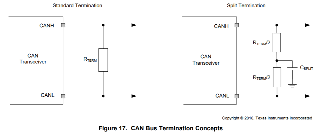
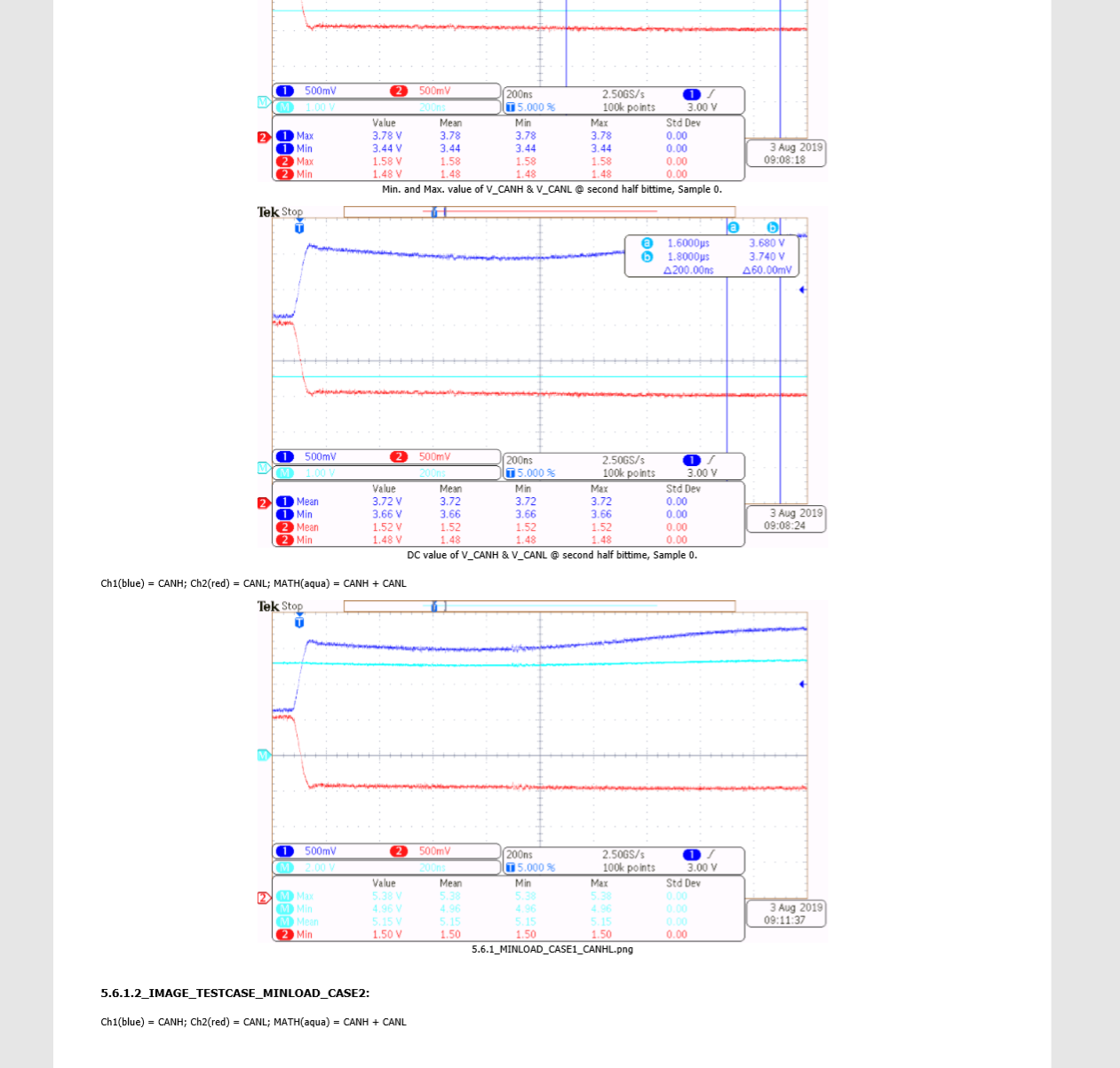
When my customer tests the symmetry of the signal, and the waveform is as below. The waveform of CANH is not good. Is there any reason about this. The schematic is as the second picture.

Thanks & Best Regards,

Sherry

  • Hi Sherry,

    Can you please check VCC as well?  CANH is pulled to VCC during dominant output periods, and I wonder if the higher supply current that is required in this state may be causing the supply to droop for some time after the transition.

    Regards,
    Max

  • Hi Max,

    Thanks for your quick reply!

    Yes, the customer said at the VCC pin, there is also another circuit. They will give me the VCC waveform tomorrow. If the waveform of VCC also droop, what should we do? Adding capacitor at the VCC pin? How large is the value?

    Thanks & Best Regards,

    Sherry

  • Sherry,

    There are a few things you could look into:

     - The amount of current pulled from VCC during a dominant state depends on the loading of the CAN bus.  This should be close to 60 Ohms (i.e., since there are typically two 120-Ohm termination resistances placed in parallel at opposite ends of the bus).  So, you should be careful to not go significantly lower in resistance from this (for example, if you have more than two terminating nodes on a network).

     - The amount of supply droop for a given load current would then depend on a few factors:

    - The load regulation ability of the regulator (which determines its transient response) and the maximum output current (which should not be exceeded).  These could be addressed by modifying the regulator circuitry.

    - The effective impedance of the power distribution network on the PCB.  For example, longer or thinner power traces from the regulator output to the transceiver could introduce both additional resistance and parasitic inductance which could degrade the transient response.  The decoupling capacitor will help to compensate for this.  So, improvements could be made either by revising power routing or (more easily) via adjusting the decoupling capacitance.  In terms of value, typically 100 nF is suitable for most applications.  If droop is observed with this value, though, you could try placing additional higher capacitances in parallel.

    Regards,
    Max

  • Hi Sherry,

    Were you able to debug this issue any further?  Please let me know if there is any further help I can provide.

    Regards,
    Max

  • Hi Max,

    Thanks for your explanation.

    In the datasheet, the termination resistor is 120ohm. But you said there are typically two 120-Ohm termination resistances placed in parallel at opposite ends of the bus. I'm confused.

    Thanks & Best Regards,

    Sherry

  • Hi Sherry,

    Those example schematics show one termination circuit each.  On a CAN bus, you would use two of these circuits.  Typically one would be placed at each furthest end.  Please let me know if this isn't clear.

    Regards,
    Max