This thread has been locked.

If you have a related question, please click the "Ask a related question" button in the top right corner. The newly created question will be automatically linked to this question.

TUSB8042: I am Making an USB hub using TUSB8042. But the problem is that there is no communication and it's not working.

Part Number: TUSB8042
Other Parts Discussed in Thread: TUSB8044, HD3SS3220,

I am Making a USB hub where I have taken D+ & D- from USB and Connected to USB_DM_UP and USB_DP_UP of TUSB8042. But the problem is that there is no communication and it's not working. There is no detection and no communication in any of the ports. I am attaching a circuit diagram with this please have a look and please help me out. Thanks in advance.tusb8042.pdf

  • Hello Subhajit,

    Please check that SMBUSz is not pulled low.  If SMBUSz is low, the hub will wait in programming mode until a SMBUS host configures it.  Also, attaching blank EEPROMs will keep the hub from connecting as it will wait to program the EEPROM.  Make sure the hub has a good thermal pad connection and a proper power on reset.

    Regards,

    JMMN

  • The SMBUSz is connected to the switch until I switch it ON it is not pulled low. In other words, it is left unconnected so there is no I2C interface and there is no provision for EEPROM as well I just want it to simply perform in default configuration please have a look on the schematic.

    Thanks and Regards,

    Subhajit

  • Please check the levels on USB_VBUS, USB_R1 and XI/XO.

    I don't see any obvious issue on the schematic.

    Regards,

    JMMN

  • USB_VBUS = 3.24 V

    USB_R1 = 0.54 V

    XI = 0.75 V

    XO = 0.75 V

    These are the potential I am getting with respect to the Ground.

    Thanks for replying, If you have any insight please help me out here.

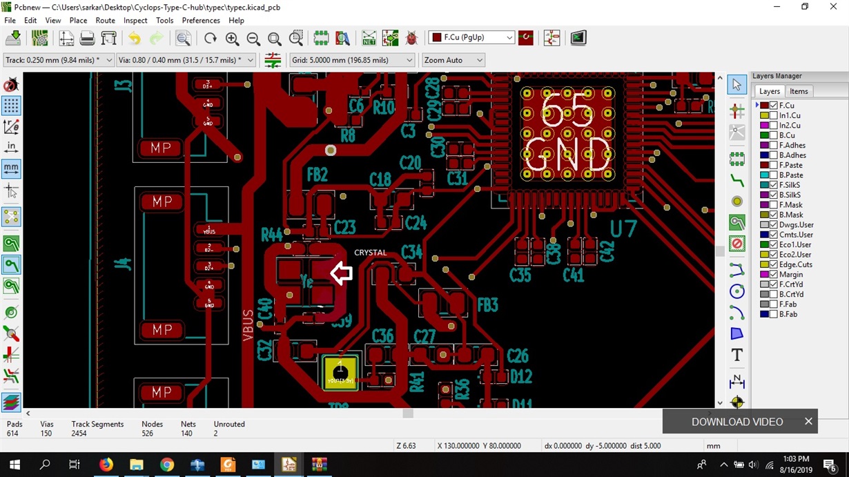
    Moreover, I would likely to let you know that the crystal placement is much farther will this create any problem or not if yes what will be the IDEAL distance to place the crystal.

    Regards,

    Subhajit 

  • Hello Subhajit,

    Looking at the circuit you have on USB_VBUS, please be aware that the voltage at the pin will be divided down to about 500 mV and the 10 uF cap should not be placed at the pin, it should be on the VBUS rail.  That capacitor could prevent the hub from enumerating.

    If removing the cap does not help, please let me know what behavior you see on the DP/DM lines on the upstream port.

    Regards,

    JMMN

  • Yeah, I removed the C46 10uf capacitance but I am still not getting any output. The potential at DP/DM pins are 0.054 V. I have directly connected the D+ and D- pins from the USB port directly to the IC and the power is maintained as well but still, there is no acknowledgement of the Pendrive and no response at the hub output.

  • Does the clock ever start?  What does the thermal pad connection look like?

    Regards,

    JMMN

  • Thats the crystal as you can see it is pretty far from the IC. I haven't Used the CRO yet but I can see the potential at XO and XI pin i.e. 0.85 V on both sides.

  • Check that USB_VBUS is ~500 mV at the pin, the clock is running and TEST pin is pulled low and SMBUS is pulled high - if you still do not see DP on the upstream port go high, it may be an assembly issue.  What is the failure rate?

    Regards,

    JMMN

  • Hii JMMN,

    Sorry, I don't know the full form of your name, I am grateful that you tolerated me so much but it's still not working the following are the output I am getting:-

    The USB_VBUS is = ~ 526 mV

    and DP = 3.2 V

    For the clock please let me know which clock you are referring to. Please tell me the PIN number.

    As per your failure rate is concerned there is no detection and recognition from my computer whenever I connect the DP/DM , VCC and GND with the circuit.

    I would be very grateful to you if you can provide me a working schematic which is working for you and can be recognized whenever I put into the USB type C cable of my computer I have searched online but there are every type of customization available but I just want to use TUSB8042  IC as a hub for 4-Port USB hub where I will put 4 -Cameras (1 camera in each port) and get the output on my Laptop. As I have purchased all the components shown in my circuit so I will be obliged if you can provide me a similar component-based schematic.

    Thanks again,

    Subhajit

  • Hello Subhajit,

    DP and VBUS are at the correct levels.  Do you see a 24 MHz clock at pins 61 and 62?

    For your test, do you just connect the hub?  Or are all the downstream devices connected too?  Is the hub self-powered or powered from VBUS?

    Our TUSB8044 EVM design is similar to what you are doing here:  http://www.ti.com/lit/ug/sllu261a/sllu261a.pdf

    Regards,

    JMMN

  • Hii JMMN,

    Well I used HD3SS3220 to draw the maximum of 15W and a single data line then I am using that to draw the power from type C connector and the data lines are separated which is then used to power the TUSB8042 and the slow speed data lines are connected to the hub.

    1. For my test I have just connected to my laptop.No device has been attached so far to the hub IC.

    2.It is powered by my laptop VBUS.

    No, PD control is done it is avoided.

    3. Yes, there is a potential but I don't see any clock cycles. 

    I don't see any I2C address as well. 

  • How are you trying to access the I2C?  Are you putting the hub in SMBUS mode?

    Regards,

    JMMN

  • For HD3S3220 it has its I2C pins mentioned I just codded an I2C scanner to see that the IC is working or not. And when I search for the address it is identical to the values mentioned it the datasheet.

    For TUSB8042 I tried to do the same thing but out of any luck. And yes I used the SMBUSz/SS_SUSPEND = 1 and then used SDA and SCL pins. but it's of no use. I can't see any address.


  • If SMBUSz is high, the hub is in I2C master mode.  You will need to set SMBUSz low to put the hub in I2C/SMBUS slave mode.  To exit this mode, the cfgactive bit needs to be set.

    REgards,

    JMMN

  • Hello Subhajit,

    Any update?

    Regards,

    JMMN

  • Closing, please post if there is an update to reopen the ticket.

    Regards,

    JMMN

  • Sorry I was out of station for the week or so due to some family problems. Thank you replied. the line where you mentioned, " To exit this mode, the cfgactive bit needs to be set." I could not get it will you please explain how to do it. Moreover, I am going for a new fabrication where all those provisions are being kept so that I can debug it with every option. It will take a month or 2 to completely get those boards in hand.

    Thanks

  • Hi Subhajit,

    Once in SMBUS mode, to exit programming mode and operate as a normal hub, the SMBUS host must set the cfgactive bit in register F8h.

    If you are building new boards, you may consider switching to TUSB8042A which has the latest spec updates. 

    http://www.ti.com/lit/an/slla445/slla445.pdf

    Regards,

    JMMN