This thread has been locked.

If you have a related question, please click the "Ask a related question" button in the top right corner. The newly created question will be automatically linked to this question.

DS90UB914A-Q1: Sporadic LOCK signal drop and minimum acceptable eye

Part Number: DS90UB914A-Q1

Hi,

We are using the DS90UB914a-q1 on our design. We are having an issue where we see the LOCK signal drop for ~1.2ms, after an hour or a couple of hours. 

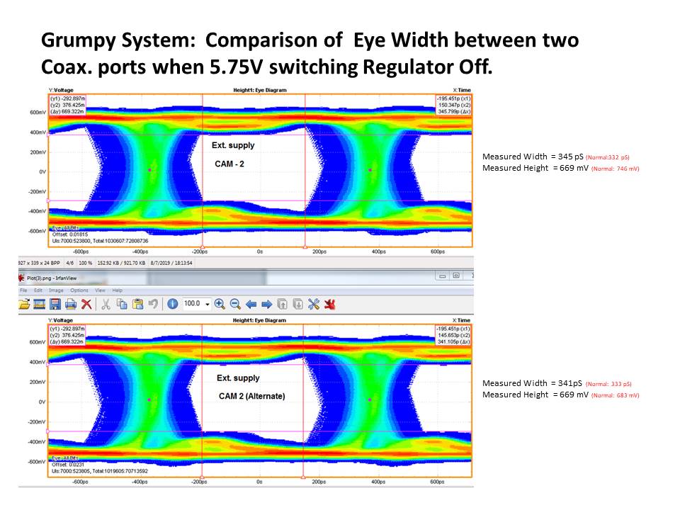
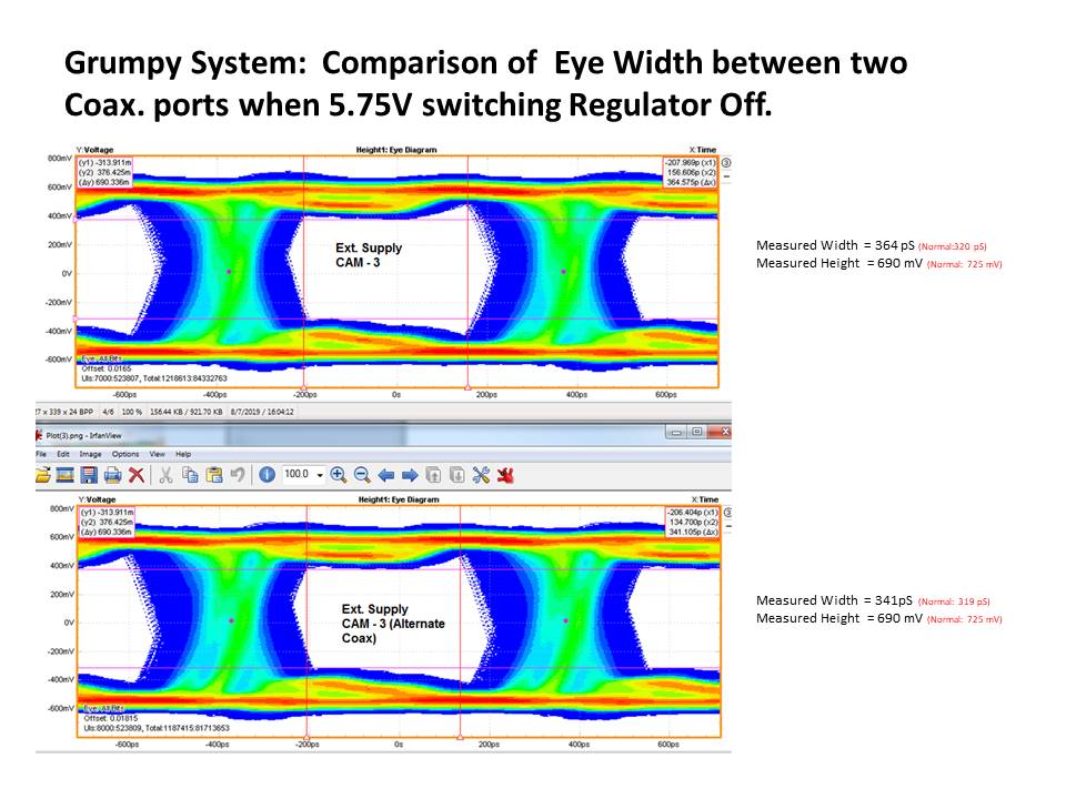
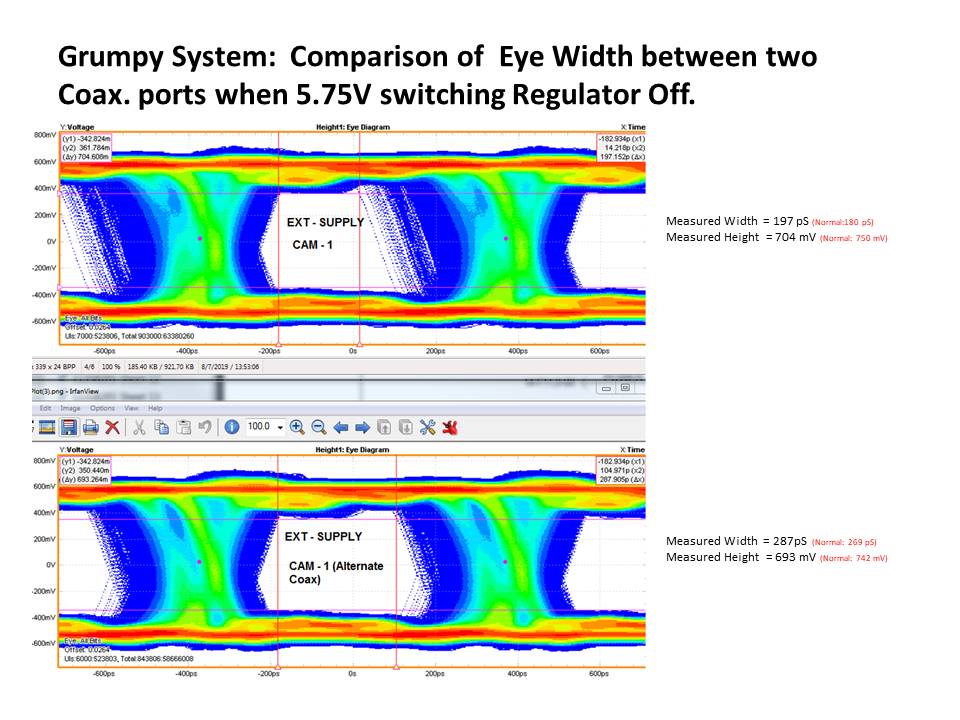
I have attached a file containing 6 eye diagrams. There are 2 eye diagrams acquired from each of the 3  deserializers we have on our board. Three are from cameras connected to RIN0 and another three cameras connected to RIN1. From board to board, the deserializer that we call CAM-1 consistently performs worse than the other 2. Furthermore RIN0 performs worse than RIN1 on this deserializer. (the camera signal connected to RIN1 is labeled ‘Alternate’ on the eye diagram). We are trying to determine the reason for this. We would appreciate any suggestions as to how to go about finding the cause.


We have looked at the PCB layout but there is nothing that stands out as a possible problem. We thought that it might be a good idea to have TI look at our PCB design.


We thought that a nearby switching power supply might be a contributing noise source but there was only a very small change in the eye width when we disabled it. All of the attached eye diagrams were acquired with this power supply disabled.


Next we plan to bypass the filter network that provides power to the remote camera and wire a coax cable directly to the .1 uF DC blocking capacitor connected to RIN0.  This will bypass the board mounted coax connector and PCB trace that connects the coax connector to the DC blocking capacitor connected to RIN0.


Also, can you provide the minimum acceptable eye width to us?
Thanks a lot for the help!

Marcus

  • Hello Marcus

             In general. we expect atleast 0.4UI eye opening. There are exceptions.,if jitter is ISI related , say due to a long cable, then we can equalize for it internally or if the jitter is low frequency jitter, we can simply track it. If the jitter is due to say an excessive return loss, or other kinds of switching noise (say due to cross talk), then we cannot correct for it.. I am assuming you captured the eye at the INPUT of the equalizer (is this correct?). Other reasons you could see excessive jitter is because of the pixel clock from the Imager into the Deserializer. I'd like to suggest you increase the AC coupling cap value (double it) , see if you can reduce the cable length. We can try some other experiments if these did not work out

    Thanks

    Vijay

  • Hello Marcus

          Any updates?

    Thanks

    Vijay

  • Hi Vijaya,


    I have enclosed  some Eye Diagram measurements from three of our systems. A separate table has been created for each system.

    The description of the three tables are:


    Table 1: System name “EP21”:Tests done with 3 different cable lengths. For each cable length, register 0x05 was set to default then retested with xC0 . Each test was repeated 3 times.


    Table 2:  System name “EMC”. Tests done with 3 different cable lengths. For each cable length, register 0x05 was set to default then retested with xC0 . Each test was done on the bench top and also inside our instrument enclosure (metal frame).


    Table 3:  System name “Bench Test Unit 4”. Tests done with 3 different cable lengths. For each cable length, register 0x05 was set to default then retested with xC0 .


    Please have the Serialize / Deserializer experts review the data in the tables below and provide comments.


    Table 1


    8/22/2019

    Description

    Measurement # 1

    Measurement # 2

    Measurement # 3

    % Difference

    Width (pS)

    Height (mV)

    Width (pS)

    Height (mV)

    Width (pS)

    Height (mV)

    EP21 800k samples

    1) 2 Feet Coax cable connected between de-serializer and Camera 1. No Layout bypass.

    264

    665

    250

    665

    258

    665

    5.3

    2) No changes done to Registers.

    1) 2 Feet Coax cable connected between de-serializer and Camera 1.

    283

    665

    281

    665

    278

    665

    1.8

    2) Write "C0" into Register #0x05h

    1) 3 Feet Coax cable connected between de-serializer and Camera 1.

    258

    678

    261

    678

    281

    678

    8.2

    2) No changes done to Registers.

    1) 3 Feet Coax cable connected between de-serializer and Camera 1.

    292

    678

    284

    678

    297

    678

    4.4

    2) Write "C0" into Register #0x05h

    1) 6 Feet Coax cable connected between de-serializer and Camera 1. 

    278

    665

    280

    678

    289

    678

    3.8

    2) No changes done to Registers.

    1) 6 Feet Coax cable connected between de-serializer and Camera 1. 

    316

    665

    306

    665

    309

    665

    3.2

    2) Write "C0" into Register #0x05h


    Table 2


    System Name

    Test Condition

    Normal Channel

    Camera # 1

    Width (pS)

    Height (mV)

    8/20/2019

    EMC system on Sample Handler

    (Sequence with GUI; 800k samples)

    1) 2 Feet Coax cable connected between de-serializer and Camera 1.
    2) No changes done to Registers.

    251

    588

    1) 2 Feet Coax cable connected between de-serializer and Camera 1.
    2) Write "C0" into Register
    #0x05h

    298

    588

    1) 3 Feet Coax cable connected between de-serializer and Camera 1. 
    2) No changes done to Registers.

    259

    597

    1) 3 Feet Coax cable connected between de-serializer and Camera 1. 
    2) Write "C0" into Register
    #0x05h

    320

    597

    1) 6 Feet Coax cable connected between de-serializer and Camera 1. 
    2) No changes done to Registers.

    308

    597

    1) 6 Feet Coax cable connected between de-serializer and Camera 1. 
    2) Write "C0" into Register
    #0x05h

    331

    593

    EMC system on Bench top

    (Sequence with GUI; 800k samples)

    1) 2 Feet Coax cable connected between de-serializer and Camera 1.
    2) No changes done to Registers.

    220

    603

    1) 2 Feet Coax cable connected between de-serializer and Camera 1.
    2) Write "C0" into Register
    #0x05h

    298

    603

    1) 3 Feet Coax cable connected between de-serializer and Camera 1.
    2) No changes done to Registers.

    272

    611

    1) 3 Feet Coax cable connected between de-serializer and Camera 1.
    2) Write "C0" into Register
    #0x05h

    320

    603

    1) 6 Feet Coax cable connected b/ between de-serializer and Camera 1.
    2) No changes done to Registers.

    309

    595

    1) 6 Feet Coax cable connected between de-serializer and Camera 1.
    2) Write "C0" into Register
    #0x05h

    341

    613


    Table 3


    System Name

    Test Condition

    Normal Channel

    Camera # 1

    Width (pS)

    Height (mV)

    8/16/2019

    Bench Test Unit 4 (Sequence with GUI; 800k samples)

    1) 2 Feet Coax cable connected between de-serializer and Camera 1.
    2) No changes done to Registers.

    212

    672

    1) 2 Feet Coax cable connected between de-serializer and Camera 1.
    2) Write "C0" into Register #0x05h

    284

    667

    1) 3 Feet Coax cable connected between de-serializer and Camera 1. 
    2) No changes done to Registers.

    242

    675

    1) 3 Feet Coax cable connected between de-serializer and Camera 1. 
    2) Write "C0" into Register #0x05h

    295

    675

    1) 6 Feet Coax cable connected between de-serializer and Camera 1. 
    2) No changes done to Registers.

    250

    675

    1) 6 Feet Coax cable connected between de-serializer and Camera 1. 
    2) Write "C0" into Register #0x05h

    291

    663


  • Hello Faisal

         What is the question here? I see that programming the LF gain register improved the eye width in almost all the cases. This seems to be short cable scenario and looks like there may be some impedance mismatch in the system. I believe you can see similar improvement(assuming an impedance mismatched system) if you connect a 1 or 2pF between + and - lines . 

    Thanks

    Vijay

  • Vijay,

    There are few question:

    1) When you say the if the jitter is ISI related you can equalize for it internally, does that mean a low width Eye is not a big concern and the IC can detect the short cable and accommodate for it? Or Are you referring to setting the correct settings on the gain register?

    2) Is CML monitor a good representation of the Signal Quality, for the FPD Link? If the reflection shows up on the FPD Link, does it also show up on the CML monitor?

    3) The Eye Height is 3X the nominal, is that indicative of overdriving?

    4) How does an improvement occur when you increase the length? How does this indicate an impedance mismatch? Keeping mind that the only things changed was the cable between the sets of pervious tests, that caused the eye width to increase.

    5) Is there a possibility that this could be an interference from radiating source, power supply, or other high speed digital signals present on the our PCB?

    Thank you

    Faisal M

  • 1) If the Jitter is ISI related, then the internal Equalizer can deal with the signal. However, in this case, it seems it is not ISI related but seems more related to Impedance mismatch which creates reflections and the internal Equalizer alone cannot deal with that. Hence the need to program the LF gain register

    2) CML monitor can give a gross , rough estimation of what is happening from a signal quality. It does not show the reflections, since the internal signal goes thru a limiting amplifier before it is presented at the CML output, so signal degradation due to reflections will not show up at CML output

    3)No this is not indicative of overdriving

    4)Reflections due to impedance are usually high frequency signal transitions that get smoothed out because a longer cable attenuates high frequency signals.Based on the behaviour you described, it seems this is related to impedance mismatch. Only way to be absolutely sure is to take S-parameter measurements on the PCB traces

    5) This is not due to interference from radiating source or power supply as those issues will not get fixed if you change the LF gain register. This is clearly some sort of correlated noise to the data that is being transmitted and there are really only 2 types of correlated noises.,Impedance  mismatches or ISI

    Thanks

    Vijay

  • Hello

    Are there any more questions related to this?

    Thanks

    Vijay

  • Since there had been no replies I am closing this issue

    Thanks

    Vijay