This thread has been locked.

If you have a related question, please click the "Ask a related question" button in the top right corner. The newly created question will be automatically linked to this question.

TPS65981: TPS65981 firmware help

Part Number: TPS65981
Other Parts Discussed in Thread: HD3SS460, , TUSB1064, TUSB564

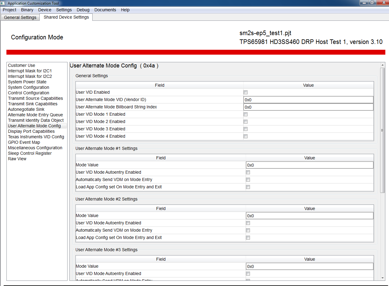
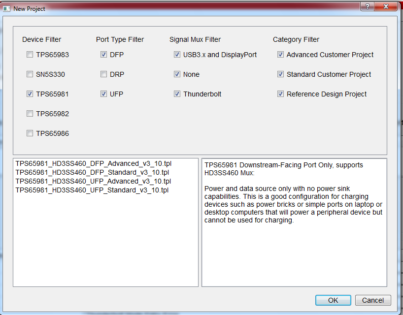
my customer uses TPS65981 and tried the implement a modulated firmware.

Right now, only  a small subset of USB-C with USB2 and Power is existing. The identification of DisplayPort and super speed doesn’t work yet.


They wish to implement the following requirements:

  • ·         Supply of 5V/3A
  • ·         USB2
  • ·         USB3 and Displayport, either unmixed or superspeed with 2-lane Displayport mixed
  • ·         Clientmode with Superspeed
  • ·         Support of Overcurrent at GPIO6
  • ·         Support of Hotplug Detect at GPIO4
  • ·         Support of  VBUS_DETECT at GPIO7
  • ·         Support of OTG Host Detect for Superspeed atGPIO2


Is there already material that I can provide existing?

Would a call with the customer directly make sense?

  • Hi Marion,

    Could you please specify in more detail what issues they are having? Which firmware version are they using?

    They can find detailed information on configuring those requirements you listed on the Firmware User's Guide. For example, the available GPIO events can be seen in Table 13-1 on page 39.

    Thank you,

    Hari

  • Hi Hari,

    nice meeting you.

    I would want to divide this topic into two parts:

    --------------------------------------------------------------------------------------

    Part one: Configuration with the tool

    Right now this is what I got from the customer:

    Could you help me find a description for those features on the left side?

    I found for example the alternate modes in this document.

    But where in this tool, could they configure GPIO4 as HotPlug detect?

    Do they need to use HD3SS460?

    Could I test the GUI without the HW, to see where certain features I listed above are configured?

    Because that link is missing for me right now.

    -------------------------------------------------------------------------------

    Part2:

    Problem switching from DP to the USB3 Superspeed.

    That occurred also on the DevKit, that's where the problem lies at the customer. But I need to explore more around this.

    Have you heard of that issue before?

    ----------------------------------------------------------------------

    I will add more info in the comment


    Thank you for your help,

    kind regards,

    Marion

  • Also, what's the difference between a low region image and a full flash image? And do they need to be flashed both?

    regarding part 2:

    Have you seen an issue like this?

    They use: For the source side they use a  TPS65981 EVM and the DP Source Board, 1m USB C cable with C to C connectors and the TPS65981EVM with a DP Sink Board.

    Kind regards,

    Marion

  • Hi Marion,

    The User Alternate Mode Config is only if you're configuring your very own alternate mode, I would not recommend configuring the features on those registers. The settings for Display Port configuration is the option directly underneath the register you are on, called "Display Port Capabilities".

    For the Hot Plug Event, GPIO4 is already preconfigured to detect that, you do not need to have any mapped events for this, it will happen automatically when operating in Display Port Alternate Mode.

    If you are using the PD controller to support Display Port Mode then yes you will need a mux. They could use the HD3SS460, but it may be a little more complex to configure for this application. Therefore, it's recommended they use either the TUSB1046/TUSB546 if they plan to use the PD controller as a Display Port Source or either TUSB1064/TUSB564 if configuring the PD controller in Display Port Sink Mode.

    To configure the other features you were mentioning such as the setting a detect event on a GPIO pin, you can configure them on the same screen from before, you can access them and set the corresponding detect by clicking on the "GPIO Event Map" option in the GUI. I will also include a link below of the GPIO Events App Note as a reference.

    The difference between low region and full flash image is that the low region is what you would flash if you were to update the firmware via I2C for instance. However, the full flash would only be necessary if you wanted to flash a whole new firmware, not necessarily just an update or a patch.

    I have not seen the DP/USB3 issue that you mentioned and provided the screenshot for, how were you able to access that screen and those settings that you were on from the GUI? 

    Helpful Documents:

    TPS65981 Datasheeet: http://www.ti.com/lit/ds/symlink/tps65981.pdf

    TPS65981 Host Technical Reference Manual: http://www.ti.com/lit/ug/slvuan1a/slvuan1a.pdf

    GPIO Events App Note: http://www.ti.com/lit/an/slva838/slva838.pdf

    Display Port Alternate Mode App Note: http://www.ti.com/lit/an/slva844b/slva844b.pdf

    Thank you,

    Hari

  • Hi Hari,

    thank you very much for such a broad answer :)

    That helps a lot!

    For now, I;m good on the question perspective.

    The pic is from the customer.

    They would want us the reproduce their setup.

    Kind regards.

    Marion

  • Hi Marion,

    I'm glad I was able to help and answer your questions. If there's no more, could you please click on the resolved button?

    Thank you,

    Hari