Other Parts Discussed in Thread: DS90UB926Q-Q1
Dear team,
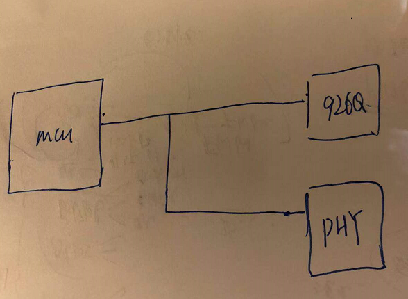
My customer use below solution in order to save the MCU's GPIO channels. DS90UB926Q-Q1 and our device DP83TC811S-Q1 won't work at the same. When 926 works, PHY will have no power supply. And when our device PHY works, 926Q has no power.
When 926Q has no power, these pins of 926 connected together with the PHY are open drain mode, and they will be HI-Z state, so 926Q won't influence our device's normal working. When 926Q works, our device has no power, if the pins of PHY connected together with the 926Q are also open drain mode, it won't influence 926Q's normal working, right?
These pins are MDC,MDIO,RX_D,RX_CLK, /RESET.
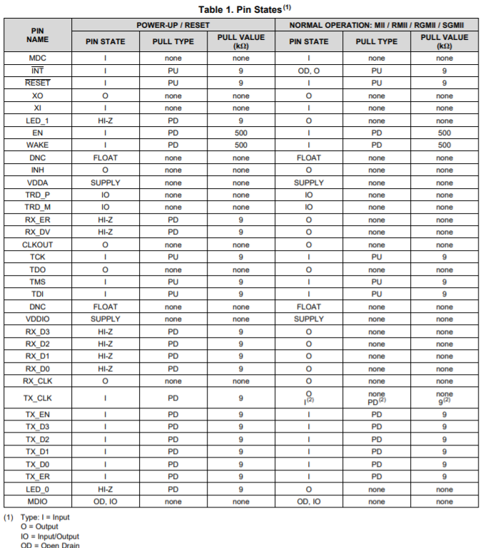
There is a pin state in our datasheet as below,it only include the power up and normal operation, not include the pin states of power down. The pin state when power down is same with the pin states when power up? If so, when the chip is in what state, 926Q's normal working is not affected? I? O? HI-Z?
Thanks & Best Regards,
Sherry


