This thread has been locked.

If you have a related question, please click the "Ask a related question" button in the top right corner. The newly created question will be automatically linked to this question.

DS90UB936-Q1: DS90UB936 cannot communicate with 935

Part Number: DS90UB936-Q1

The project needs s32v234sbc to connect to the 936 adapter board via mipi, and then connect to the lvds harness driver camera. We designed our own adapter board according to the common circuit of 936 (the circuit diagram is attached), but it can't adjust the 936-935. The line, can not see the 935 and the camera address, the camera manufacturer has been tested, has successfully matched 954-935 also recommended us to use the 954 chip, but the 954 chip can not meet the needs of two cameras because of a single channel, we only use 936 , (the circuit diagram provided by the camera manufacturer is attached as an attachment)

Asked to help review the circuit board for problems?

Request a register configuration to help design the connection?

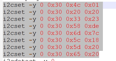
(The configuration commands we use now are as follows)

DS90UB936.pdf

ap22036_ds90ub954_mars_deserializer_rev1.pdf

  • Hello Meng,

    The REFCLK attached to 936 is 32.768 kHz according to the part number in the schematic. The REFCLK for 936/954 is required to be between 23-26MHz. 

    Best Regards,

    Casey 

  • After measurement, our 936 chip No. 5 pin REFCLK is connected to the 25M crystal oscillator, and it works normally!

  • Hello Meng,

    So does this mean that the issue is resolved?

    Thanks,

    Casey 

  • Casey 

    Hello, I am the person in charge of the project 936-935 described by meng gong. Now you and I will conduct the second description. We reviewed the REFCLK of 936 according to your suggestion and found that there is no problem with it.That is to say, the problem described before in this project still exists. The 935 and the camera cannot be found at the end of 936.Please continue to review our hardware and software.thank you

  • Hello Jiaxin,

    Ok, can you please post the correct schematic? It seems that the components in the schematic you posted before do not match the actual design based on the above comments.

    Thank You,

    Casey

  • Above is our actual 936 switchboard circuit diagram.

  • Jiaxin,

    I still don't understand what you are telling me. If I reference the schematic you provided then the REFCLK is the wrong frequency so I don't believe the schematic you provided is correct. 

    There is also another issue I see which is that the regulator that is supposed to be providing the 1.8V rail is a fixed 3.3V regulator:

    If you have provided 3.3V to the 1.8V supply pins then you have probably damaged the chip because the abs max for those pins is 2.16V. 

    Best Regards,

    Casey 

  • Sorry Casey,

    that was our hardware engineer who was lazy and copied and pasted the name of the component with the same shape. The chip on the circuit board is the correct output of 1.8v. You can ignore the name of the chip and see the labeled voltage of the pin

  • Casey 

    We have found that the mode configuration voltage of 935 is 0V, which means that the mode of 935 is cs-2 Synchronous mode -- fpd-link IIIClock reference derived from deserializer. So, how many volts should we configure the pin voltage of mode 936?Configure why schema?thank you

    Best Regards,

    jiaxin

  • Hello Jiaxin,

    Please configure 936 for MODE 4 from table 2 in the datasheet. 

    Thanks,

    Casey 

  • Casey 

    No matter how I configure it, what I see on register 0x5B is 0x00 only。Can you recommend an i2c setting for the 936 paired with the 935?For example, set register 0x58 to 0x58...。

    thank you

    jiaxin

  • Jiaxin,

    There is no required register configuration for 936 to link with 935 in synchronous mode. Please ensure that all power rails are at the correct voltage, PDB is high, the REFCLK is the correct frequency, and the 935/936 have a proper cable connection. Also verify that the PoC voltage is applied to power the remote camera. 

    Best Regards,

    Casey 

  • Casey 

    Hello, I changed the mode of the pin resistor configuration for mode4, then I tried a lot of kinds of software configuration register, but still cannot see 935 address, in 936 registers 0 x5b is always 0 x00 never change, also only 936 on the i2c bus address, could you please recommend a pair of 935 936 software configuration register?In addition, please analyze the reasons for this phenomenon.

    thank you!

    jiaxin

  • Hello Jiaxin,

    Again, there is no required register configuration if both devices are mode strapped properly and all the correct power/clocks are provided to the ICs. I would suggest taking the following actions:

    - Verify each power rail at the 936 by probing the power pins at the device and check against the voltage requirements in the datasheet 

    - Verify the REFCLK at the 936 is the correct frequency (25MHz) and it meets the jitter requirements in the datasheet 

    - Double check the PDB pin to ensure it is going high after the power supplies have stabilized as per the power sequence requirements in the datasheet 

    - Disconnect the 935 and probe the output of the coax connector at the 936 side while the device is powered on. It should be sending out at 50MHz signal trying to establish link to the remote serializer by default

    Please let me know the results of these checks. 

    Best Regards,

    Casey