This thread has been locked.

If you have a related question, please click the "Ask a related question" button in the top right corner. The newly created question will be automatically linked to this question.

DS90UB954-Q1: Bypass capacitors for VDDs

Part Number: DS90UB954-Q1

Hi team,

We design the circuit for 954.

There is an explanation about the capacitance value in the pin function of the data sheet, but I think that at least the necessary capacitance value is written.

Therefore, the capacity is actually determined according to the typical connection diagram in the data sheet.

So I have some questions about capacitance selection.

#1

In the typical connection diagram of the data sheet, the capacitor closest to the VDD pin is described as 0.01uF-0.1uF.

How should users decide capacitor from this range?

I think that I we should choose the smallest 0.01uF because of high frequency noise, but is there a case where we should choose 0.1uF?

#2

According to the pin function, 10uF and 0.01uF are required for the VDD11_CSI pin.

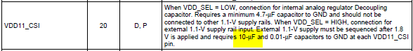
However, in Figure 44. Typical connection diagram in the data sheet it has only 1uF, which is less than 10uF.

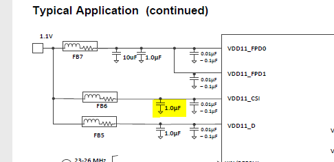
I understand that 10uF of the Pin Functions is the minimum, which should I follow?

Best regards,

Tomoaki Yoshida

  • Hello Tomoaki,


    1.) Smaller capacitors are used for high frequency noise filtering, but the capacitor value depends on the user to choose what they want for their needs. We give recommendations for the ranges of values permitted. 0.1uF capacitors are used for filtering noises in the middle frequencies range (neither high nor low).


    2.) Could you clarify if you’re using an external power source?

    The diagram in the datasheet is an example of a typical application and varies with the use case. We recommend 0.01uF, but will need to clarify how you’re using the power source.

    Best,

    Liban H.

  • Hi Liban-san,

    Thank you for your support.

    2.) We intend to allow both external and internal supply.

     When using internal regulator, it is reauired more than 4.7uF.

     When using external power supply, it is required 10 uF and 0.01 uF.

     This is not enough because the datasheet block diagram has only 1 uF.

     Is it okay if I put 10 uF instead of 1 uF?


    Best regards,

    Tomoaki Yoshida

  • Hi Tomoaki,

    We would recommend that you use the 10uF capacitor since this is what is recommended in the datasheet.

    Best,

    Liban H.