This thread has been locked.

If you have a related question, please click the "Ask a related question" button in the top right corner. The newly created question will be automatically linked to this question.

SN75DP159: Few quesiton

Part Number: SN75DP159

Hi Sirs,

Sorry to bother you.

Our issue is 

We are currently testing the ACER 4K30Hz function normally.

But when the resolution is adjusted to 4K 60Hz, it will sometimes be black and then restored.
When the movie is broadcast, the image disappears with the screen once and disappears for about 1 second to 2 seconds.

We have few question on DP159.

1. How could we check we are using DDC Snoop Mode or not?

2. How could we dump out for DP159 register ?

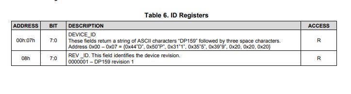
3. As below pic, we can be seen coming to our ADDRESS at 01 (BA), then the value is 00110001. We have a problem with [1:0] changing from 2’b01 to 2’b10.

4. We would  like to know about the difference between 01 and 10?

5. Where is the difference in the address setting?

  • Shu-Cheng

    1. The snoop configuration is implemented where the SDA/SCL from the source is connected directly to the SDA/SCL of the sink. The DP159 will connect its SDA_SNK and SCL_SNK pins to this link in order for the DP159 to configure the TMDS_CLOCK_RATIO_STATUS bit. Care must be taken when this configuration is being implemented as the voltage levels for DDC between the source and sink may be different, 3.3 V vs 5 V.

    2. It looks like you are able to correctly dump out the DP159 registers since the Registers 0x00h to 0x08h dump out the correct Device_ID and Rev_ID.

    3. HDMI2.0 provides support for data rates between 3.4Gbps and 6Gbps. The difference is the crossover point for "01" it is 1Gbps, for "10" it is 3.4Gbps.

    Are you seeing TMDS_CLOCK_RATIO_STATUS toggle from 0 to 1 when changing resolution from 4k@30Hz to 4k@60Hz? Per the HDMI2.0 spec, when a source changes from 4k@30Hz to 4k60Hz or from 4k@60Hz to 4k@30Hz, 

    • The source shall suspend the transmission of the TMDS clock and data.
    • Change the TMDS_BIT_CLOCK_Ratio bit.
    • Allow min of 1ms and max of 100ms before resuming transmission of TMDS clock and data

    Thanks

    David

  • Hi David,

    Thanks for your reply.

    0x00h to 0x08h spec is show I2C register, please refer as below

    But in the front is the Extended DDC register.

    Both of them are same?

  • Shu-Cheng

    No. Here is the DP159 ID Register

    The DP-HDMI adapter buffer and extended DDC register for Type 2 capability is accessed at target addresses 80h (Write) and 81h (Read). The capability and control registers are mapped to DDC address space. The registers are accessible using I2C-over-AUX transaction support or through DDC signaling.

    Thanks

    David