Part Number: TPS25740B
Hello,
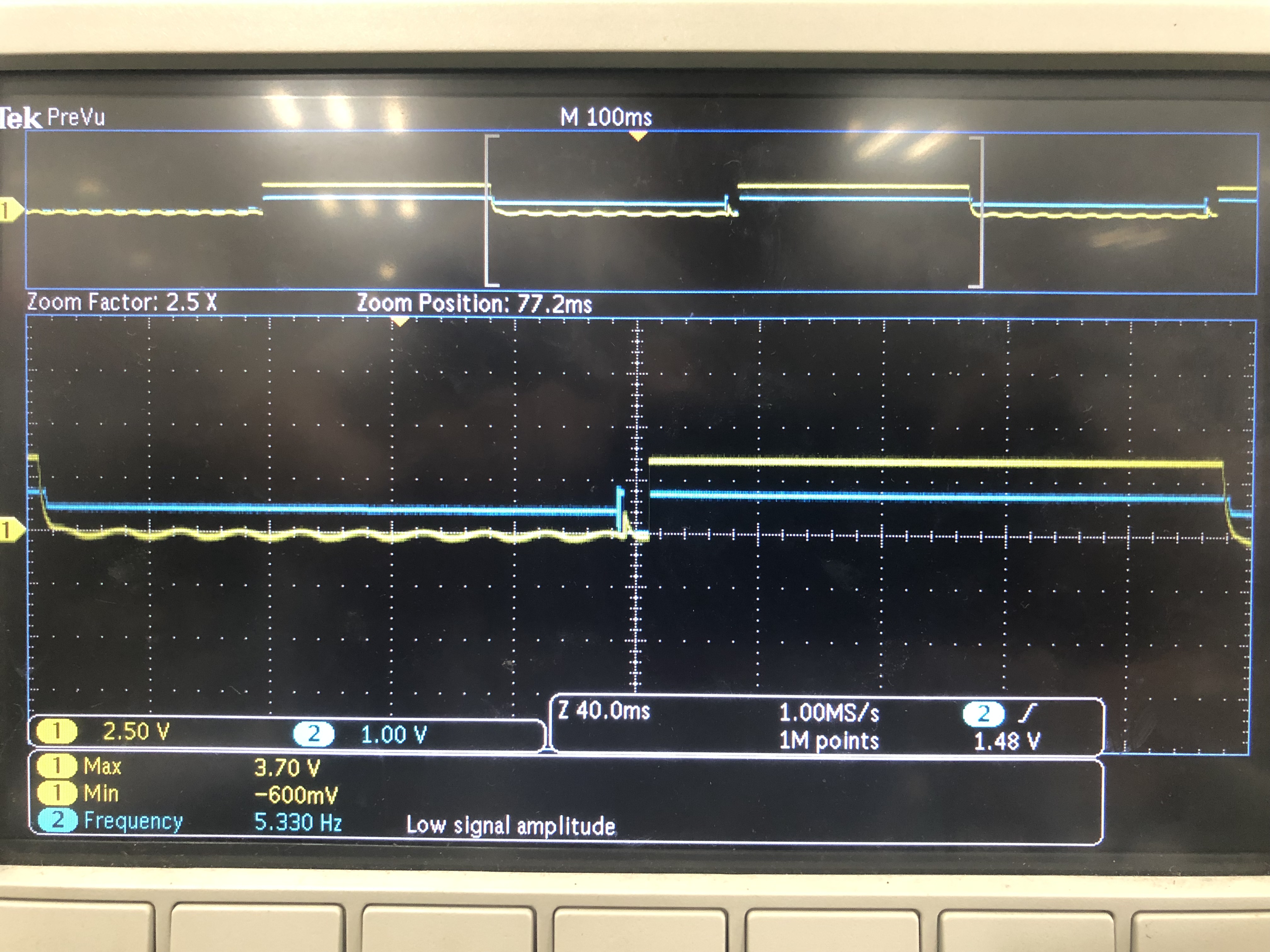
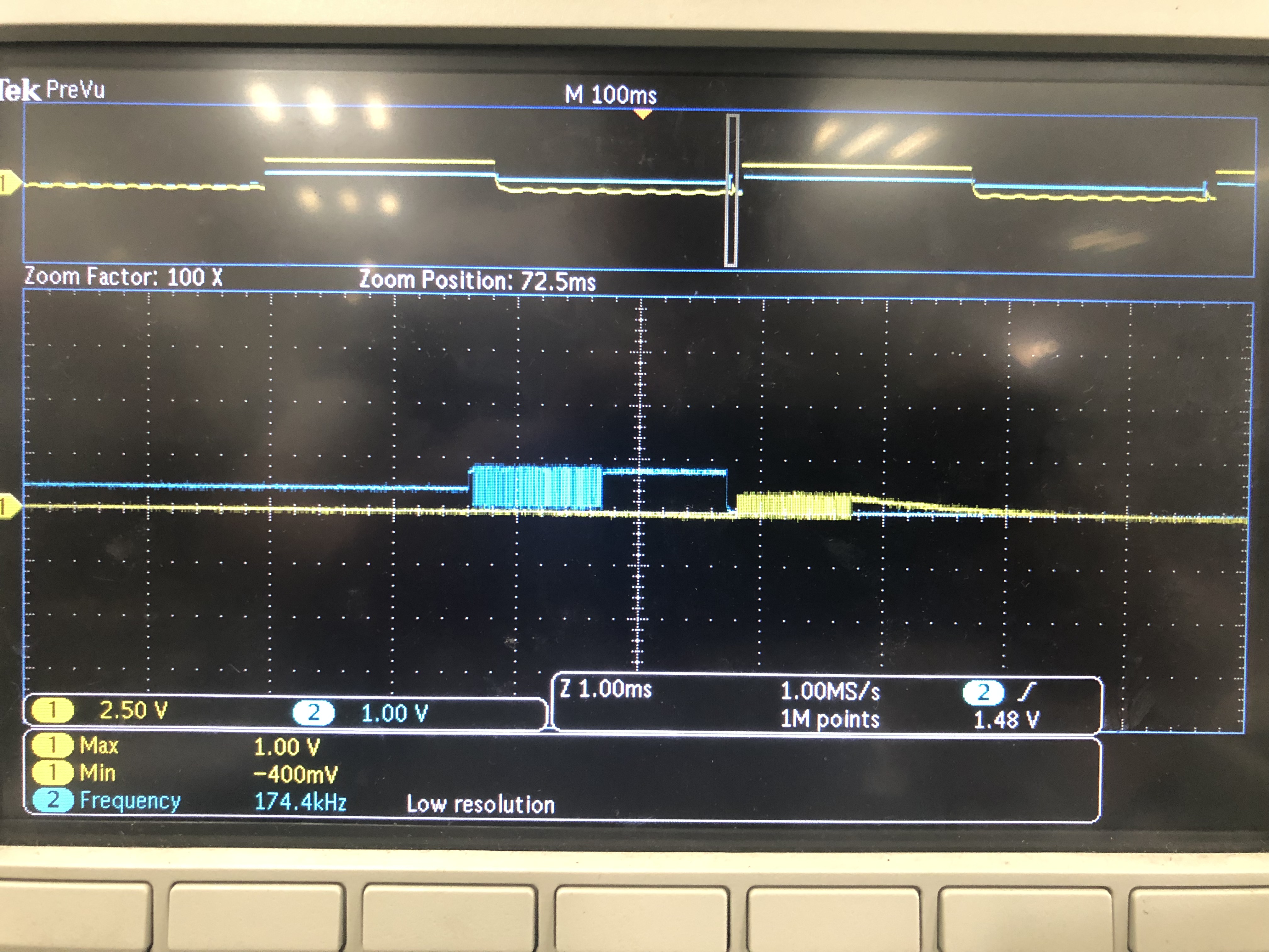
I used the TPS25740b as a PD protocol communication. The design of the chip is based on the solution provided at www.ti.com.cn/.../TIDA-01622. The test module uses a 5V input power supply. After the scammer is connected, it expects to output 5V, run at no load, and then test the signal on the CC line. The signal waveform is as shown in the figure, where yellow is CC1 and blue is CC2. Looking at the waveform seems to trigger the protection, but I can't find the reason and hope to get help.