This thread has been locked.

If you have a related question, please click the "Ask a related question" button in the top right corner. The newly created question will be automatically linked to this question.

TPS65987D: Internal Switch Turning off during dead battery mode power up

Part Number: TPS65987D
Other Parts Discussed in Thread: TPD6S300A

On my new control board with a TPS65987D I am struggling to get my dead battery mode working. 

My schematic is configured in a similar manner as the eval kit (Vbus is tied to both of the bus inputs on the 65897, the PPHV1 is a dedicated sink path and the PPHV2 is a dedicated source path). On my target, I am using my host microcontroller to perform configuration over I2C which doesn't play a role yet since I'm having difficulty getting the power to stabilize to power this host.  There is no SPI flash and there is no external switch.

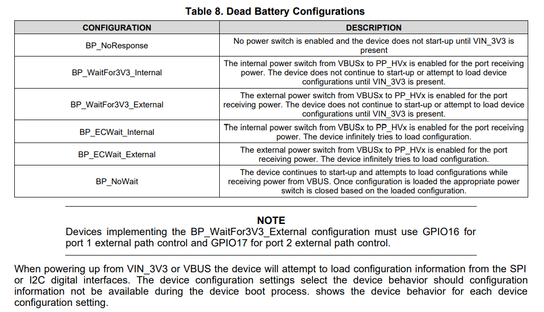
I am trying to use boot config mode 3 with BP_NoWait to get the system up and running. 

My expectation is that the 5V from a USB source cable would enable the internal switches for PPHV1, allow my external system 3.3V LDO to power up which then would power my microcontroller which would then configure the 65987 using the I2C port.  

Unfortunately, about 20ms after the internal switches turn on, they shut right back off again.  I am not sure what mechanism is turning them off.   70ms later, the internal switch turns on again.  This cycling repeats indefinitely while the 5V source is plugged into the USB-C connector.

Am I tripping some sort of protection shutdown in the part?  Is the part getting confused by seeing the 3.3V external voltage appear on the Vin pin from my LDO prompting it to turn off its own internal LDO path and reboot?

At this stage, there are no I2C communications programmed to come out of my microcontroller.

Any feedback would be greatly appreciated!

  • Hi Aaron,

    You may want to check the ADCIN1 values again and see that they match the configurations.

    However, I see that you're using BP_NoWait, in this configuration though, the PD controller will start up and attempt to load the configuration settings while being powered from VBUS. But, since you don't have SPI Flash or I2C programming available, the configurations won't be loaded and therefore, you won't receive the function you are expecting. I would recommend looking into using a different configuration such as the internal wait configurations perhaps. You may look at the different configurations on Tables 5, 6 and 7 in the datasheet here: https://www.ti.com/lit/ds/symlink/tps65987d.pdf

    From my understanding, you are attempting to power the PD controller in dead battery mode from the USB cable. Once it's powered you want to power the microcontroller from the PD controller so you can program it via I2C, is this correct? Another thing to note would be to see if the microcontroller is attempting to pull more current than possible from the PD controller and the USB cable. I would recommend measuring VBUS to ensure it's what you expect it to be as well.

    Thank you,

    Hari

  • Hi Hari,

    Thanks for the reply.  It was not clear to me from the datasheet and the pre-configuration options in the boot section that you needed the I2C or the SPI flash to enter those preconfiguration states.  I thought that was the point having some ROM encoded configurations in the first place.  

    Are you telling me that all the preconfigurations will not actually load into the application until there is a I2C link ready to go?  

    For the most part, I am just hoping that I can get the internal sink path switches to automatically turn on so that I can run my external regulator to power my system from Vbus (not your internal 3.3V LDO).  In this way, I desire to power my system from the Vbus supply, not your PD controller supply which I understand is current limited.  My system should only be drawing 10's of milliamps, I will take a measurement to confirm.

    Regards,

    -Aaron

  • Hi Hari,

    I have determined that my load current draw is about 30mA when my regulator switches on.  My cycling of the internal switch behavior was the result of my microcontroller coming up with the reset line asserting active high.  I have corrected that problem and now my internal power switch path is behaving on a standard 5V USB charger.  

    I am still having difficulty getting a smart laptop USB-C charger to come alive with 5V, I see about 3V appear on the CC1 line when I plug in my cord but the adapter never turns its 5V source on.  When I plug the same adapter into the eval board operating in configuration mode 3 just as my circuit is, the 5V does come out of the laptop charger.

    I would love additional clarification on the configuration mode 3 and what happens when I have no SPI flash or I2C link active from the micro during the boot process.

    Regards,

    -Aaron

  • Hi Hari,

    I have a theory as to why my smart adapter might not be cooperating in the sense that the 5V rail is never coming up - I am using the same protection circuit as the Eval board, the TPS6S300A.  Unlike the Eval board however, in my circuit, I did not connect the RPD pins to the CC pins on that protection IC.  My thinking at the time was that my main PD controller, the TPS65987D already was taking care of the RPD pull down resistors in the dead battery mode and I didn't want two sets of these resistors in parallel.

    What I now believe is happening is that since the TPS6S300A has internal switches that prevent the CC lines from reaching the PD controller chip until the part is powered.  Since this protection chip derives its power only after the Vbus turns on (and it never does), these CC lines never get the benefit of the Rpd resistors that are built into the TPS65987D.  

    Therefore, it appears the Rpd resistors must come from the TPS6S300 since it is the only impedance presented to the connector before power is applied.

    I will try connecting that path to see if that gets my smart adapter back up and running.

    I am still interested in finding out if configuration mode 3 should be negotiating 15V (the maximum input) or if I'll only ever get 5V out of my smart adapter and it will require me sending I2C commands with my micro to ask for the 15V.

    Hope to close out this issue once I complete my test.  Thanks for the support.

    -Aaron

  • Hi Aaron,

    I will get back to you with feedback on Wednesday. am traveling at the moment and will be back into the office by then.

    Thank you,

    Hari

  • Hi Aaron,

    To get back to you, no I am saying that the preconfigurations will load into the application, however, I see on the datasheet that since you are also using the BP_NoWait dead battery mode configuration, then it will depend. I will include a screenshot below of the part I am referencing in the datasheet, it is in the last paragraph.

    As far as receiving the 15V contract, I will continue to look into your setup to understand the functionality and get back to you on that.

    For the TPD6S300A however, yes I think you should be connecting the RPD pins to CC pins on that as well. In a dead battery condition, the OVP FETs on the TPD6S300A are turned off for protection, so with the PD controller also in dead battery, they should be connected. Below is a paragraph from the datasheet explaining a little better and in detail the functionality.

    Were you able to test this and see the results?

    Thank you,

    Hari

  • Thanks for sending me that explanation and the reference in the datasheet for using the protection IC.  After I connected in the Rpd feature on the protection IC, I did get the power path to turn on.  Thanks for continuing to search on the ability to negotiate a sink contract for >5V from PD controller at boot time without SPI or I2C intervention.